Leo's Assignment 8: Final Project!
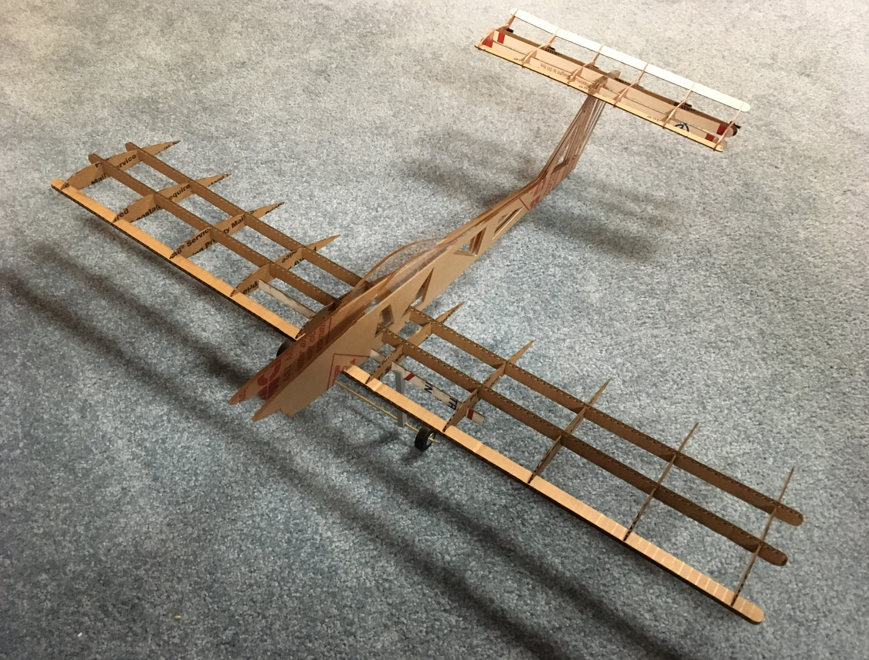
Here is all the documentation for assignment 8!

Here is all the documentation for assignment 8!
Available on github.com at https://github.com/LeoSalemann/LeoSalemann.github.io/tree/master/hcde598/hw08
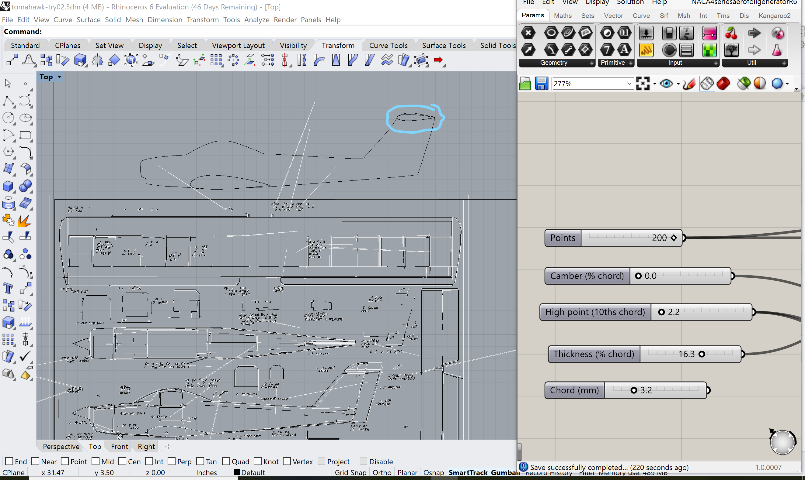
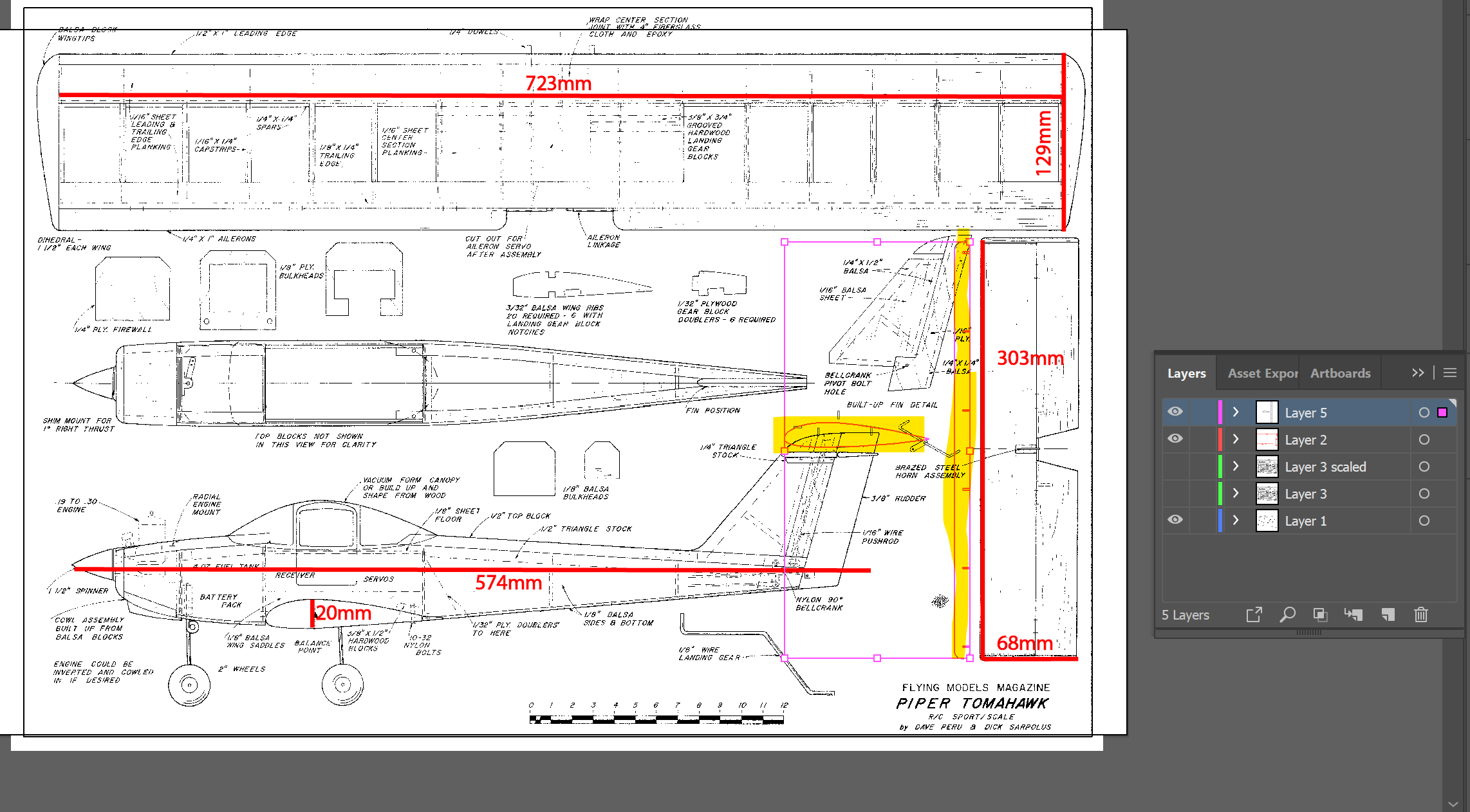
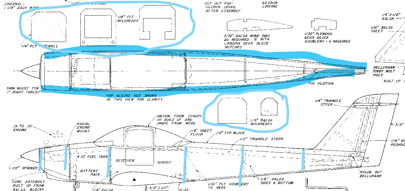
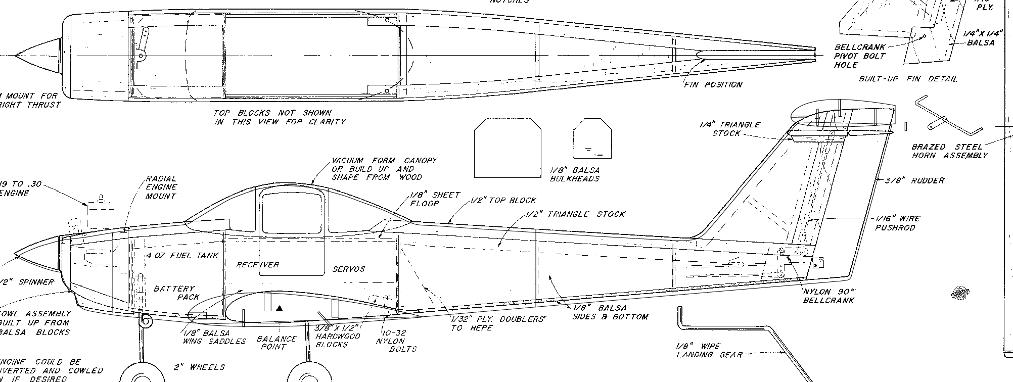
Make sure I'm In inches. Measure the plan from Assignment 7, get a scale factor. Scale in Adobe Illustrator (easier than in Rhino), export to SVG, pull into Rhino, retrace the fuselage. Grab a copy of the Grashopper airfoil generator from Assignment 3, generate the wing.
Also generate stabilizer (horizontal tail) with grashopper.
Bring out the wing spar generator from Assignment 3 Turn off the millimeter conversion. Start with the basic wing spar lenth and slot count.
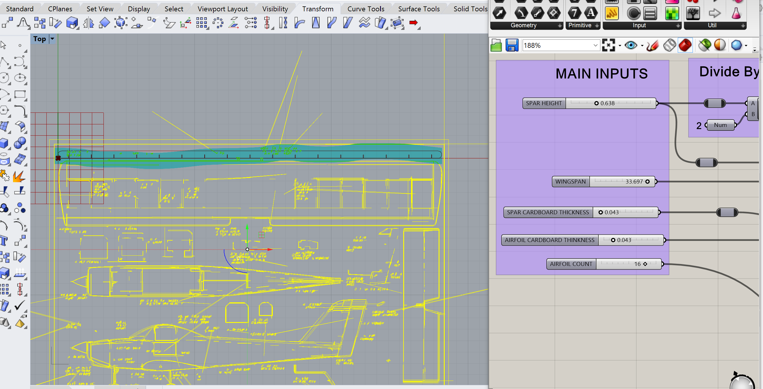
Compare wing spar vs. the airfoil, dial in the height.
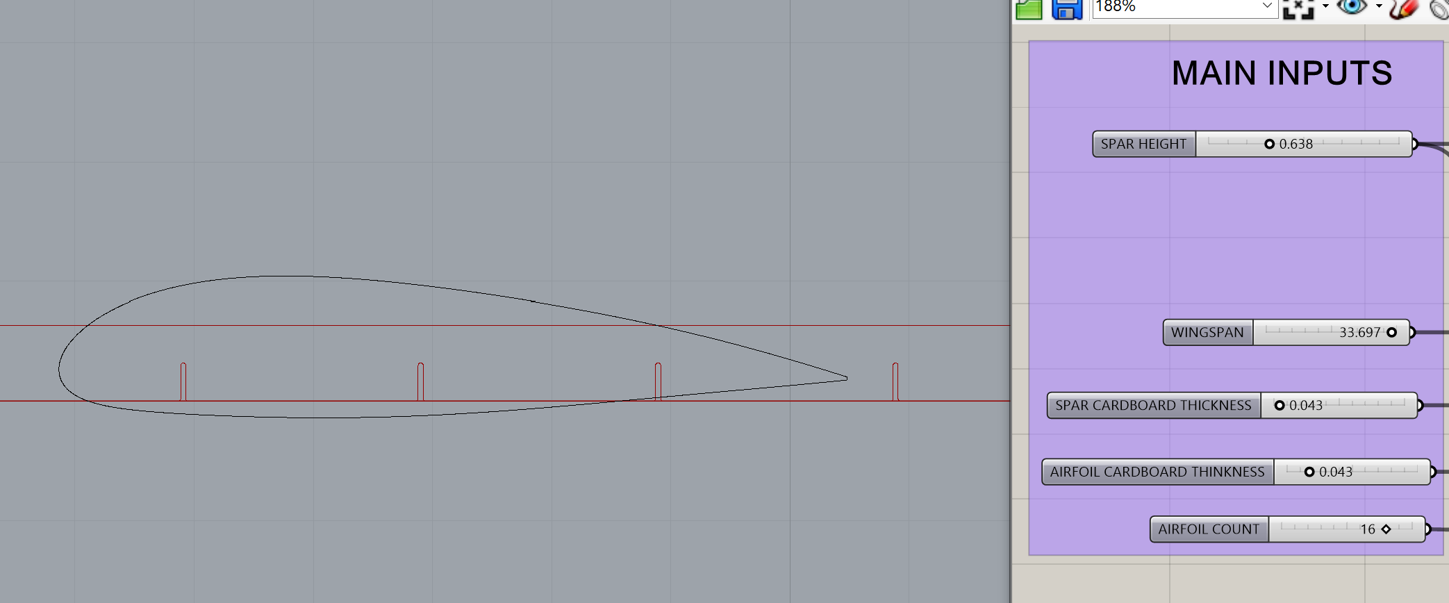
Move on to the elevator.
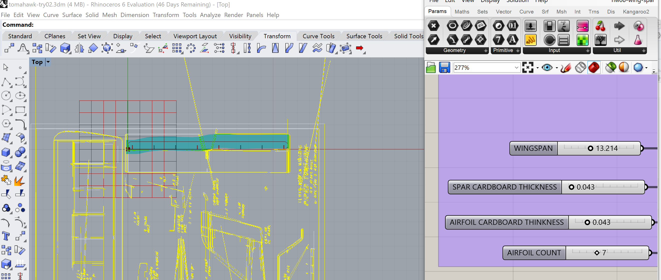
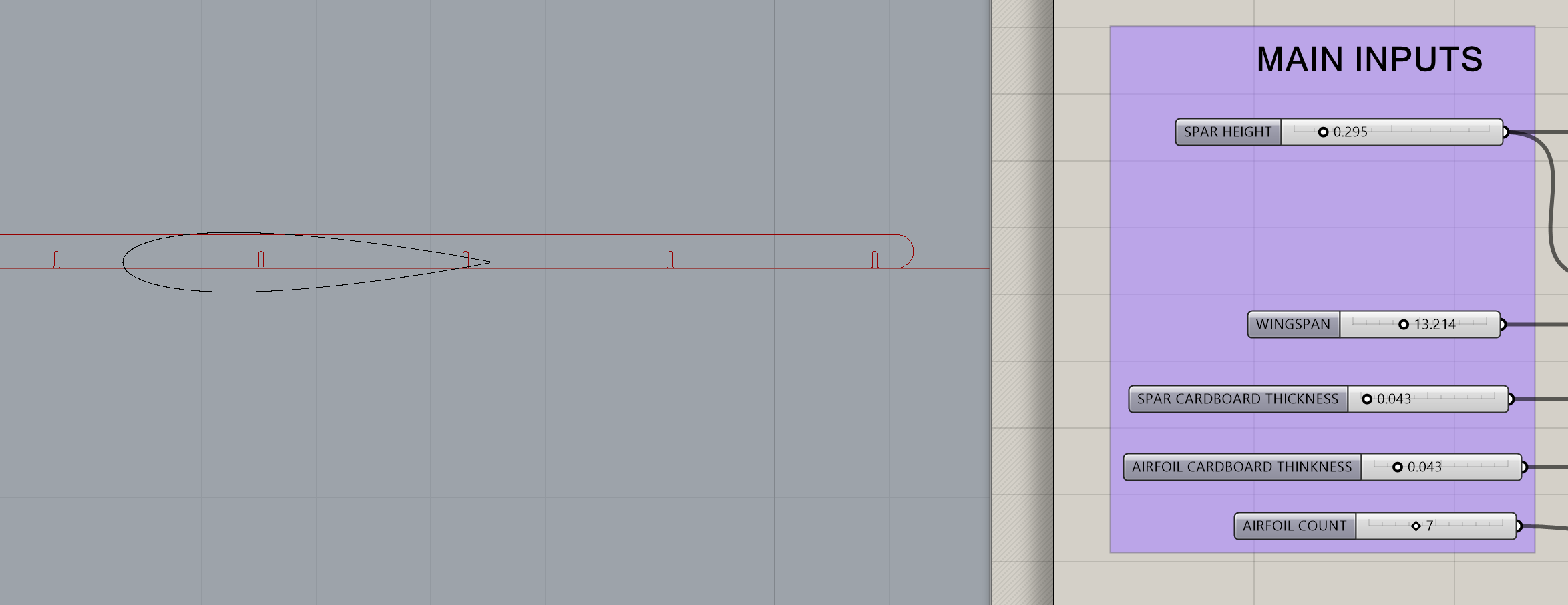
I started by charging off in inches, mostly based of the bed sizes of the Epilog Laser Cutters. The thought occurs my careful notch work from Assignment 3 (Airfoil Lamp) was in millimeters. Also I'm having scaling problems when I go from Adobe Illustrator into Rhino. Grashopper Airfoil generator wants millimeters, Dremel 3D wants millimeters, Adobe Illstrator can be converted. Take a deep breath, go back to Illustrator, re-do my dimentions in mm.
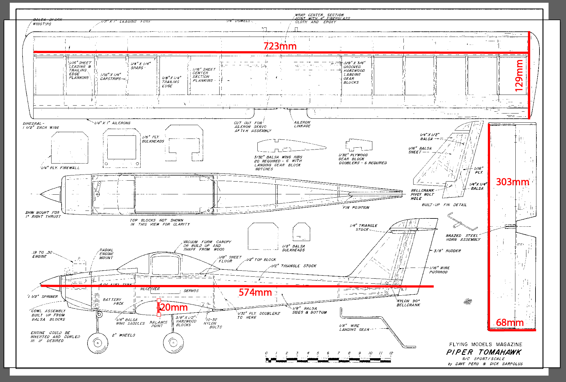
Configure Rhino for millimeters. Redo the Illustrator -> Rhino workflow. Measure wing in Rhino; compare to AI.
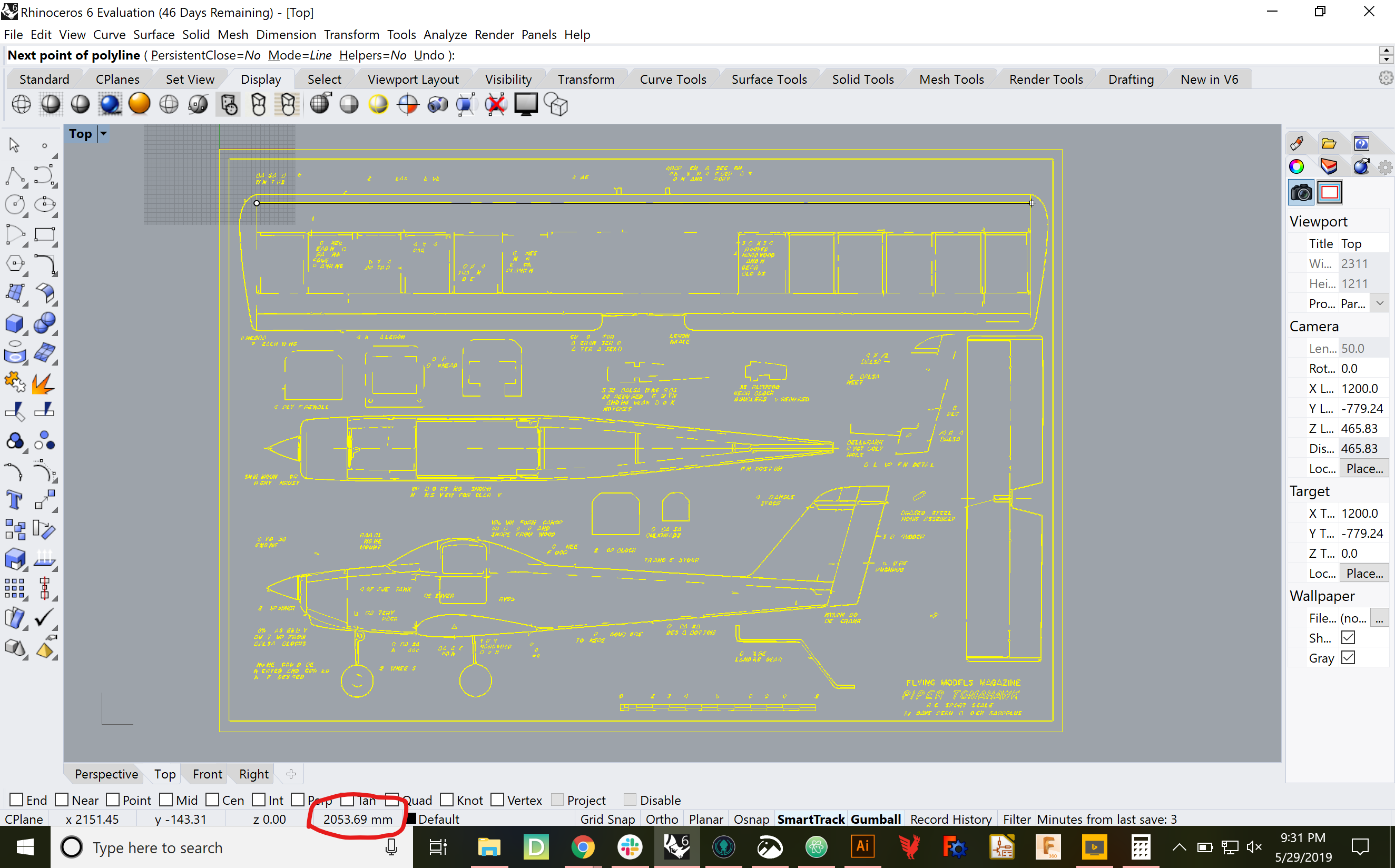
Back to Illustrator, scale by 723/2053.59 = 0.352, re-export to SVG, re-import to Rhino and ...
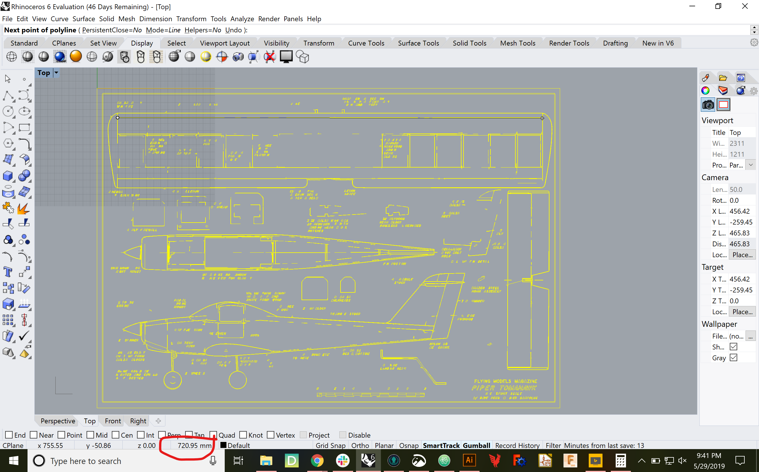
721 mm. Not bad at all. Time to save, commit, push, then re-do the airfoil and spar generation.
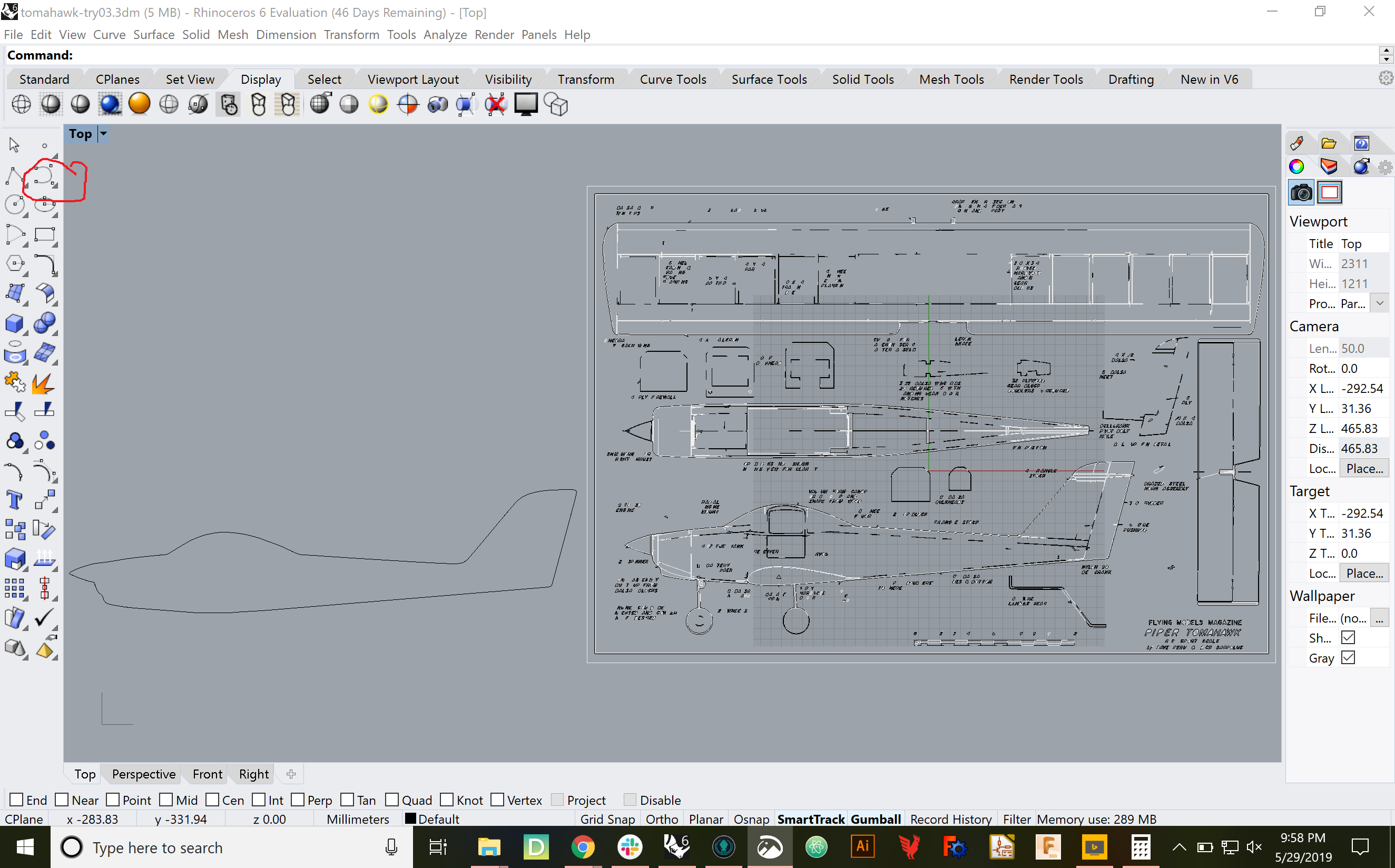
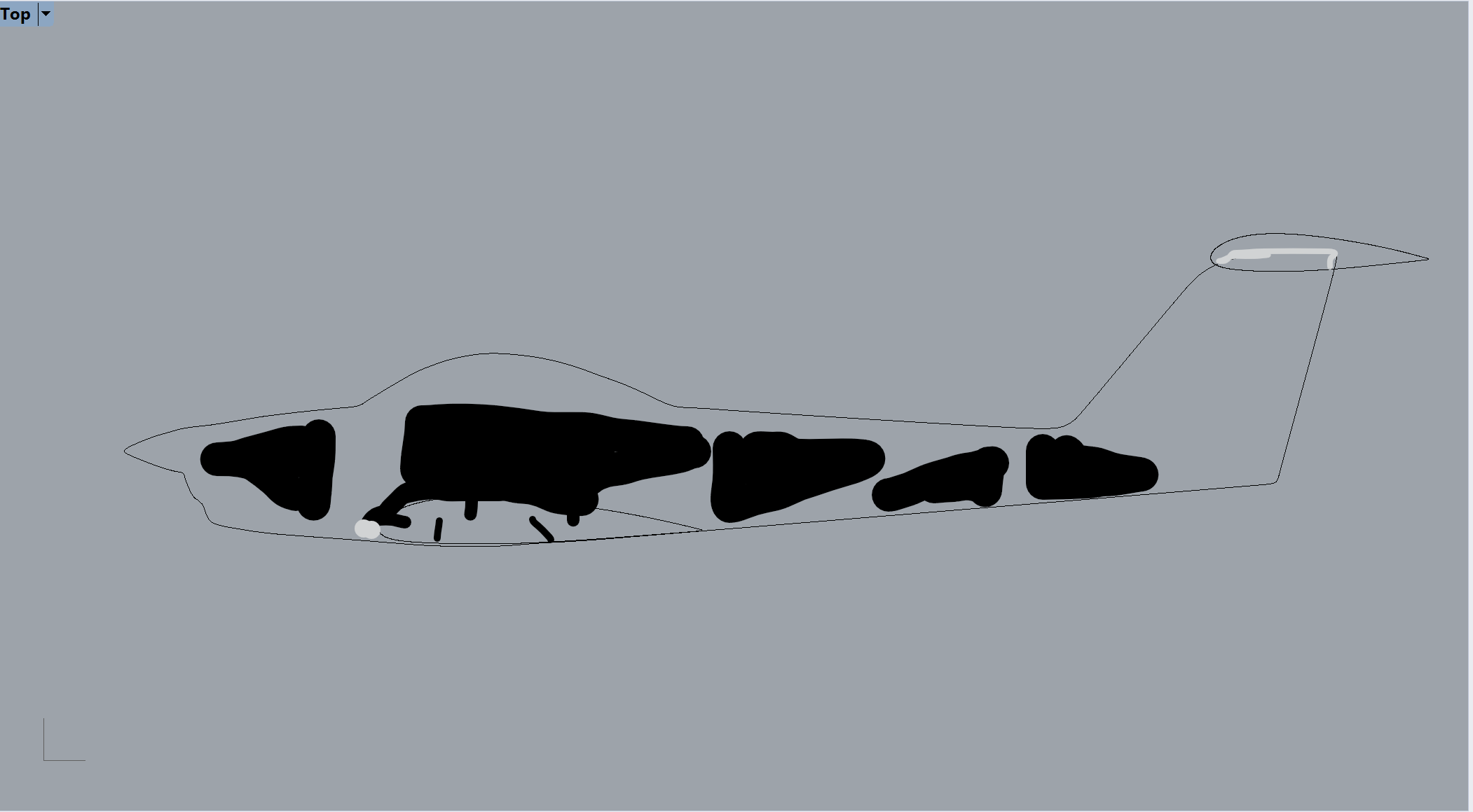
Re-trace the fuselage in Rhino, using Control Point Curves as Usual.
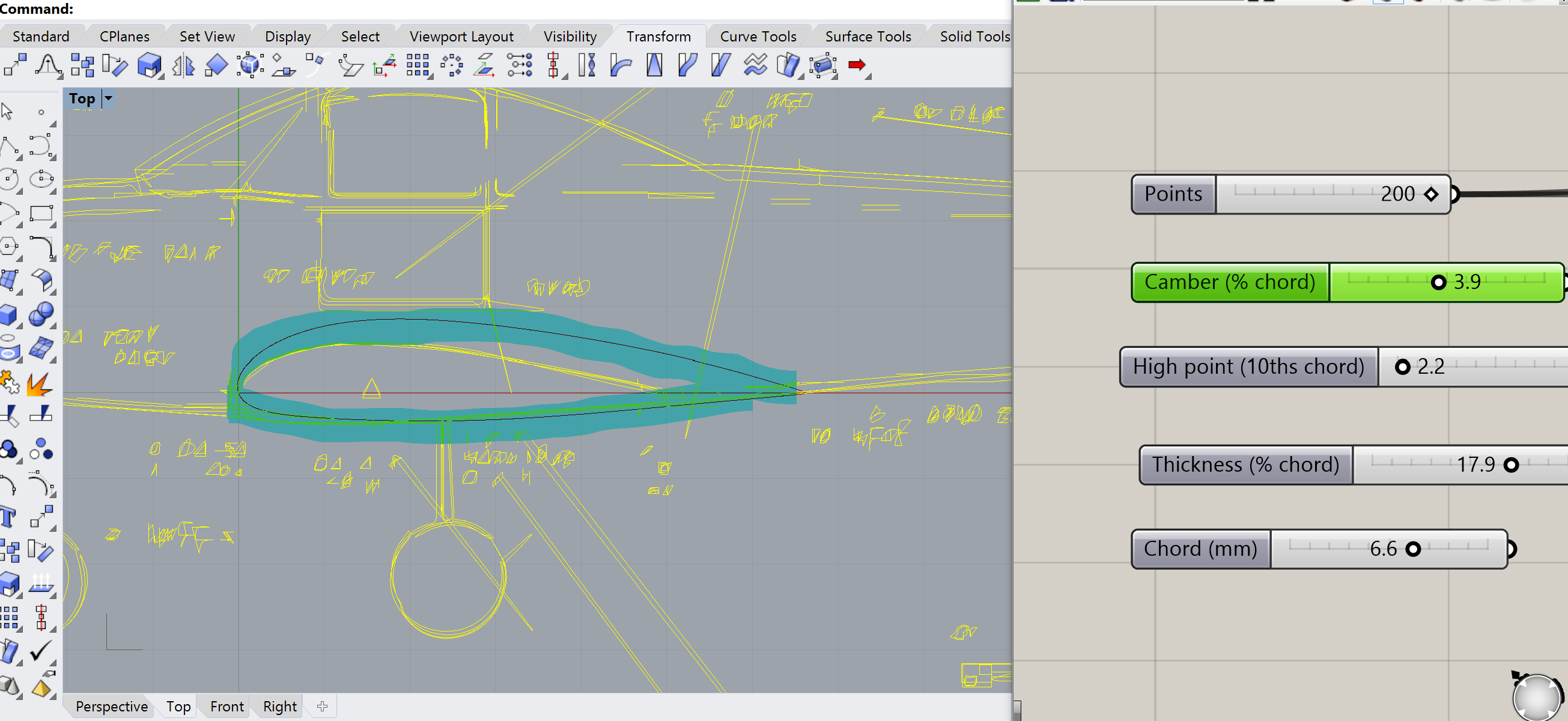
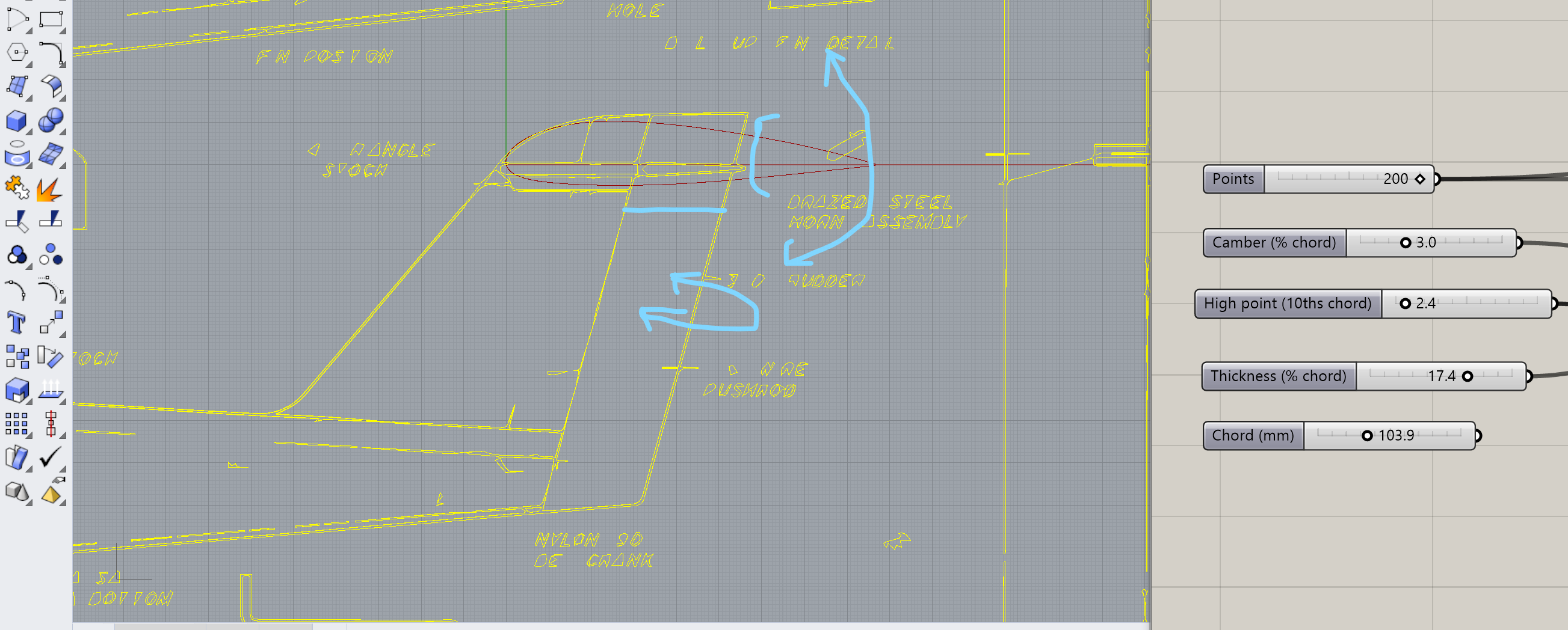
Pull up the Dr. Paterson's airfoil generator from assignment 3 , line up the airfoil from the Tomahawk plans and roll my own. Start with the 129mm chord length measured from the plans, and set the thicknness to 20/129 = 15.5% of chord. I can actually get pretty close.

That said, I'm gonna go a little bigger, so I have more room for ailerons and hopefully fowler flaps.

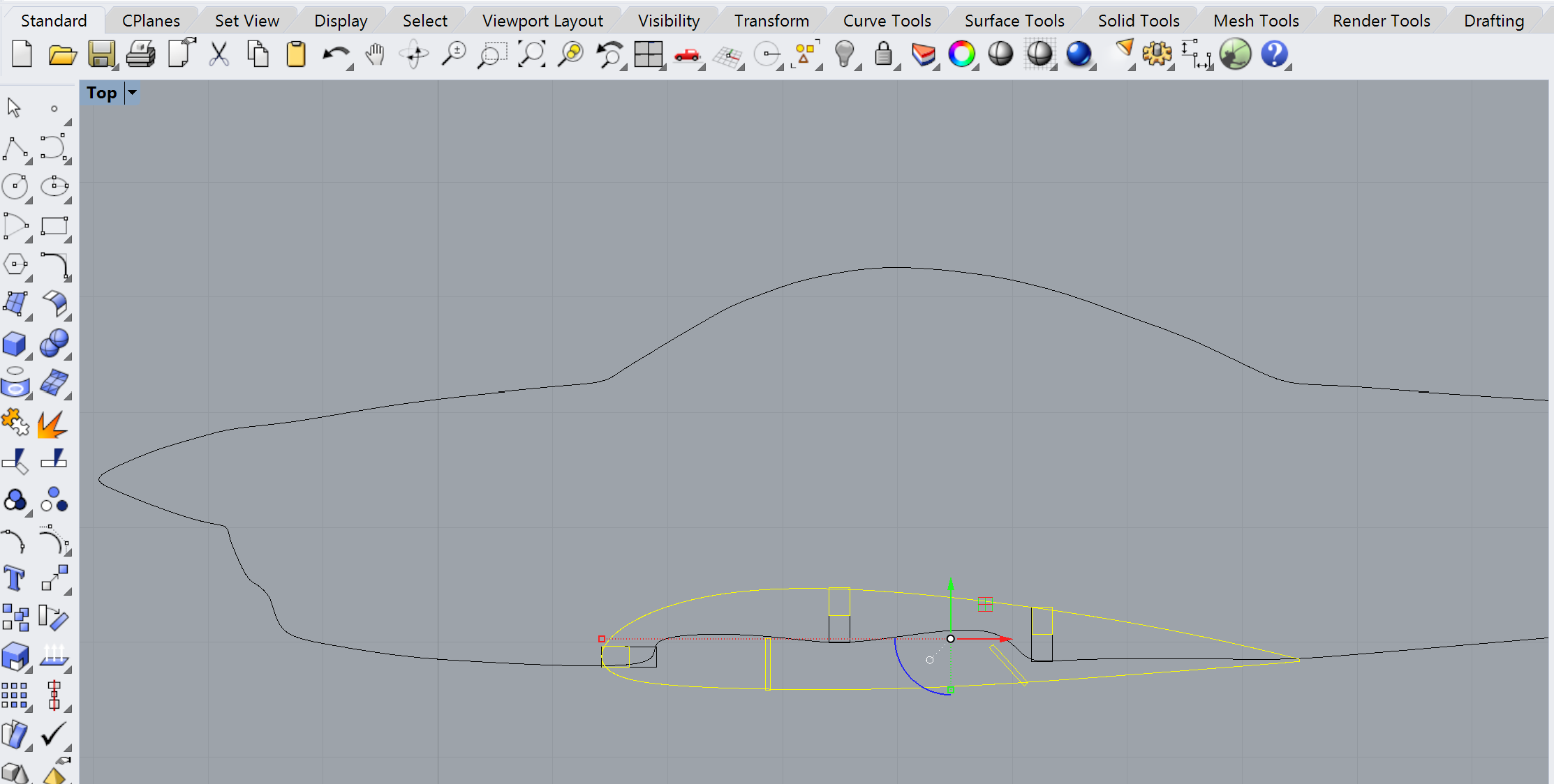
Bake the airfoil, move it over by the traced fuselage, line up for horizontal stabilizer. Here's my next "cheat." To avoid having to cut v-notches to prevent the elevator and rudder from interfering, I'm going to just extend the chord so the elevator portion simply overhangs the vertical tail. If I set my rudder the right way, no interferance (I hope.)
On to the wing spars, regenerating for millimeters. Use the spar generator from Assignment 3 , but first think about cardboard thickness. In Assignment 3, all the cardboard was the US postal stuff. This time, the airfoils will still be the USPS thin cardboard, while the spars will be science fair trifold or somtehing similar. So, the slots cut into the spar will be thin, to accomodate the airfoils. I can use the slot thicknesses from Assignment 3. The slots cut into the airfoils will be thick, to accomodate the thick spar. I might be able to dig up the thickness from one of my early gauge studies, but I can worry about that later. Important thing is I can use the Assignment 3 spar generator with its existing slot dimensions
Turns out the Spar generator actually operates in inches, but it kinda doesn't matter. I can prettymuch "eyeball it" to get the spar lengh to agree with the wing span on the original plan.
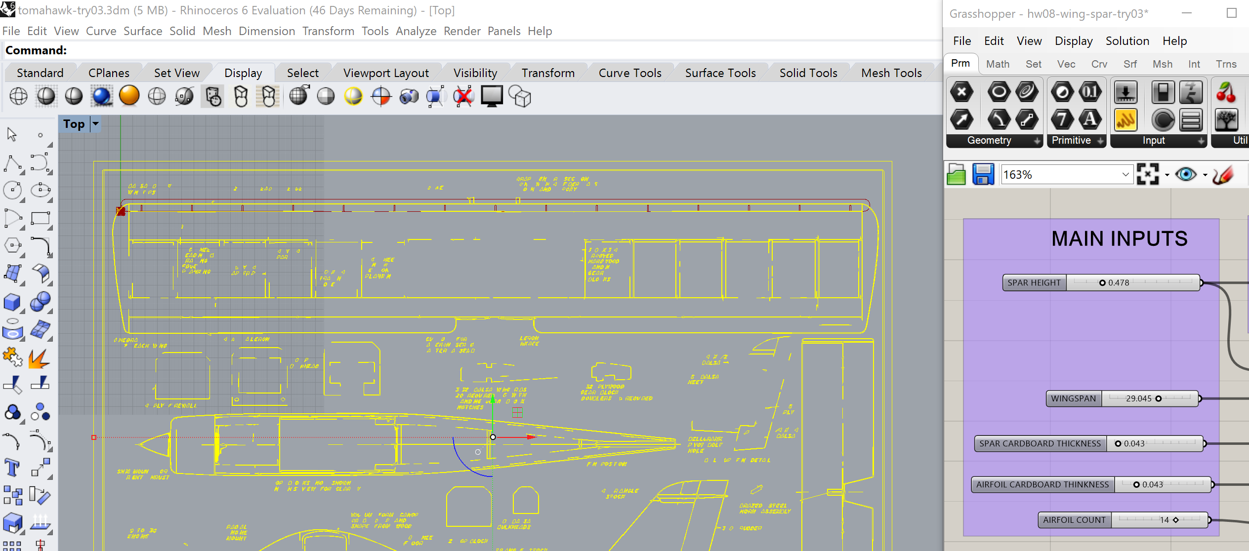
Similarly, I can compare it to the airfoil I just made to make sure the spar is narrow enough.

I gonna probalby hafta do some prelminary laser cuts pretty soon. But first imma thinken the spar, then just be more careful where I place along the airfoil profile.

Bake, and move on to the elevator spar. This one looks small enough that I can probalby use USPS cardboard for the spar as well as airfoils.
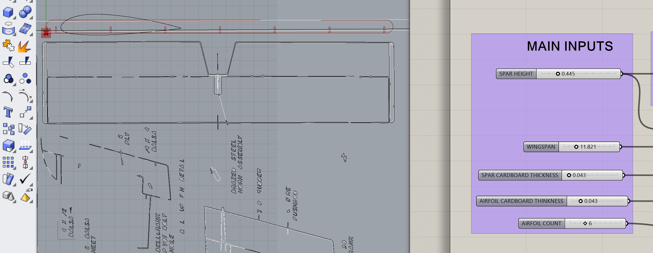
Take some caliper measurements
An evening appointment went longer than planned, no time to CAD tonight. All I can do is plan for tomorrow and the weekend.
Use an even number of airfoils, not odd. I had a plan to cut some lightening holes in the fuselage, and sort of "carve out" airfoil shapes to match the wing and horizontal stablizer. Forget that. Use an even number of airfoils, then shape the fuselage with an "airfoil-shaped dent" with notches for the spars to slide in. Notches should only be on the fuselage side, so the wing can slide left and right as necessary for centering.
Friday's for Cadding Cardboard Ignore all the moving control surfaces. First get "fixed" wing and stablizer done. Do some slot-test studies for cardboard-to-acrylic. Do slot & hole studies with FR-1.
Satruday Morning's for Shopping
Start Saturday with 3D printing It's a long-lead item. Landing gear is simple. Re-use the slots from the Assignment 3 lamp, but the other end needs to work with whatever wire landing gear I found in the morning. After that move on to ...
A lot of that will probably bleed into Sunday and next week
It's a simple little wing, all made with USPS cardboard. Should go quick, so let's get on with it. First-off, redo the spar because (a) I lost my save from last time and (b) I need to re do it for an even number of airfoils anyway.
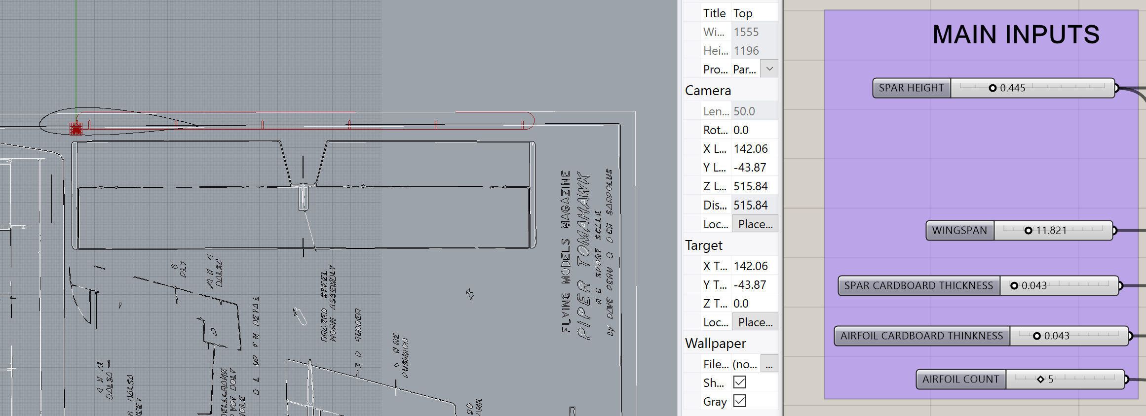
Can I do the Extrusion in OnShape? Wonder if I can export the 2d curves as their own 3dm's for OnShape, rather than extrude and cap in Rhino like last time.
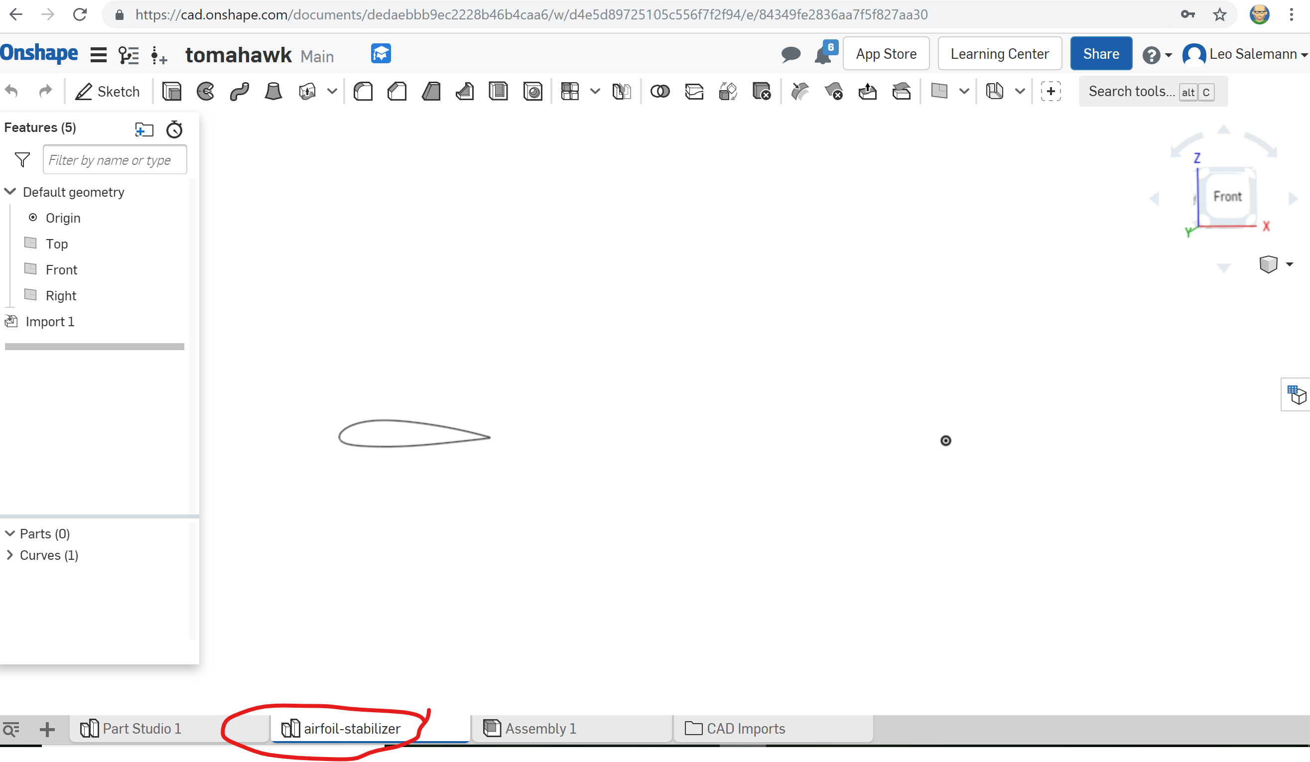
Actually, yes! I'm gonna do it again though, this time moving it to origin in Rhino first, and naming it stabilizer-horiz-airfoil so my names will sort nicely when I add a spar, and when I deal with vertical vs. horizontal stabilizers.
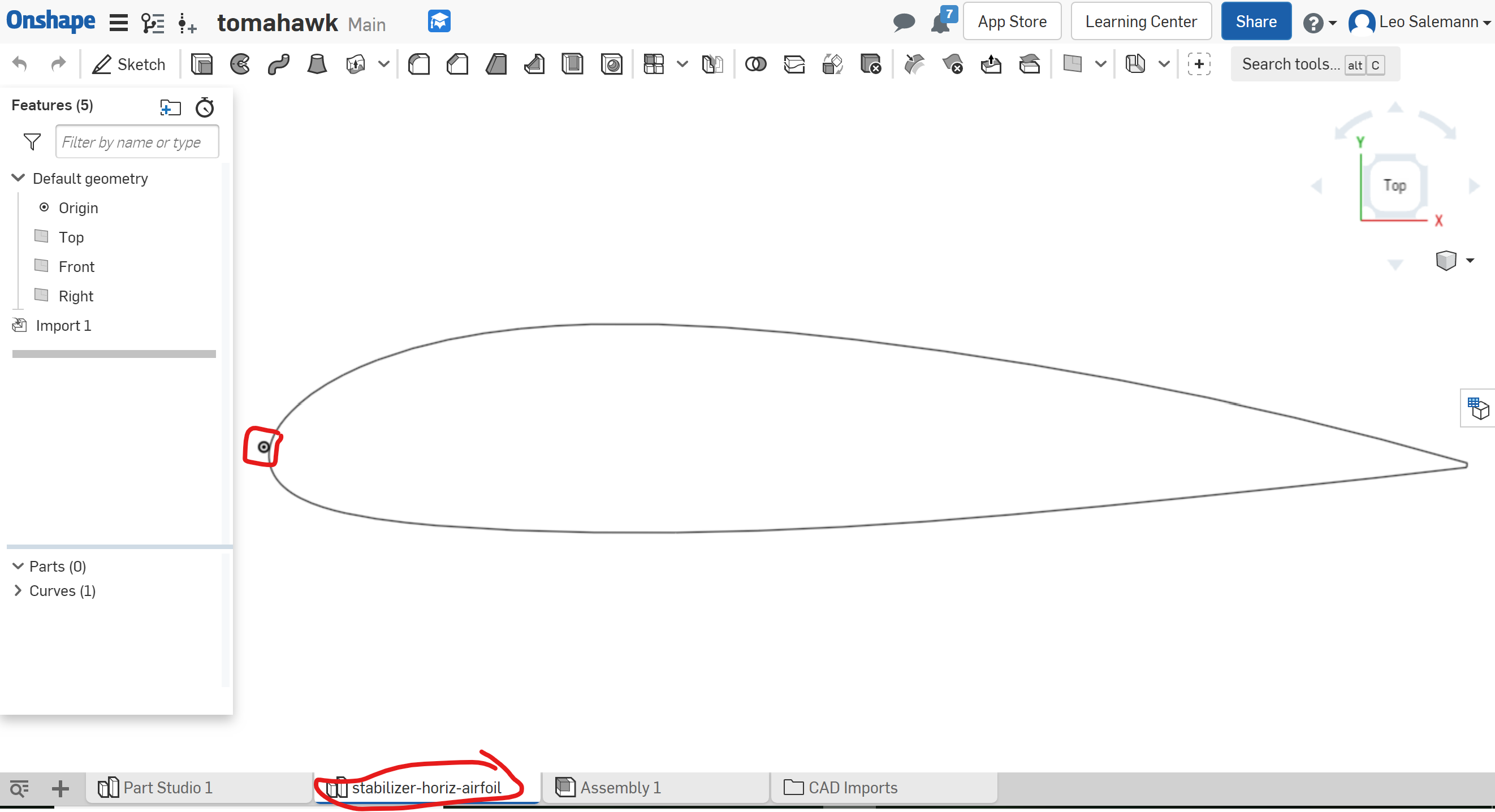
So it looks like extruding in Rhino is easier after all. A 2D import into OnShape leaves me with a plain curve that I can't turn into a sketch or do anything useful with. Extruded Rhino files come in as actual Parts which can be dimensioned. Dimensions seem to check out. I just need to convert 0.138 inches ("Notch Size" from Assignment 3) to 3.482 mm.

Okay, now move the spar over to origin in Rhino, extrude by 3.482 mm, and import into OnShape. Now let's see if I can cut notches in OnShape instead of Rhino.
Or, Maybe Not. I can't find anything that will "cut" one 3d shape from another. Back to Rhino. Use my spar generator to bake an "airfiol slot." Line them up at varous ponints along the stabilizer airfoil curve. No trims, no cuts, nothing fancy. Just let the lasercutter do that part. Export to AI format, 1mm = 1mm.
Looks like the scaling held together.
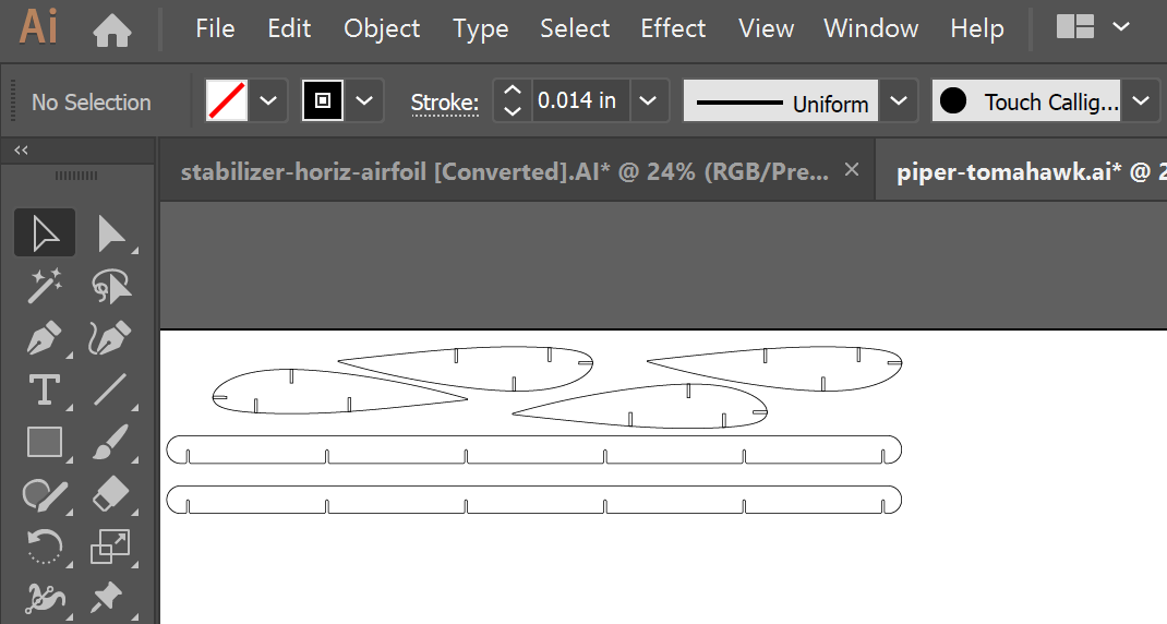
Copy, paste move a few times so I have multiple spars and airfoils. Need to group the slots with the airfoil (feels lame, I should probaby trim in Rhino like an adult). Bunch everything up tight in one corner to conserve cardboard. Just doing a test-fit at this point.
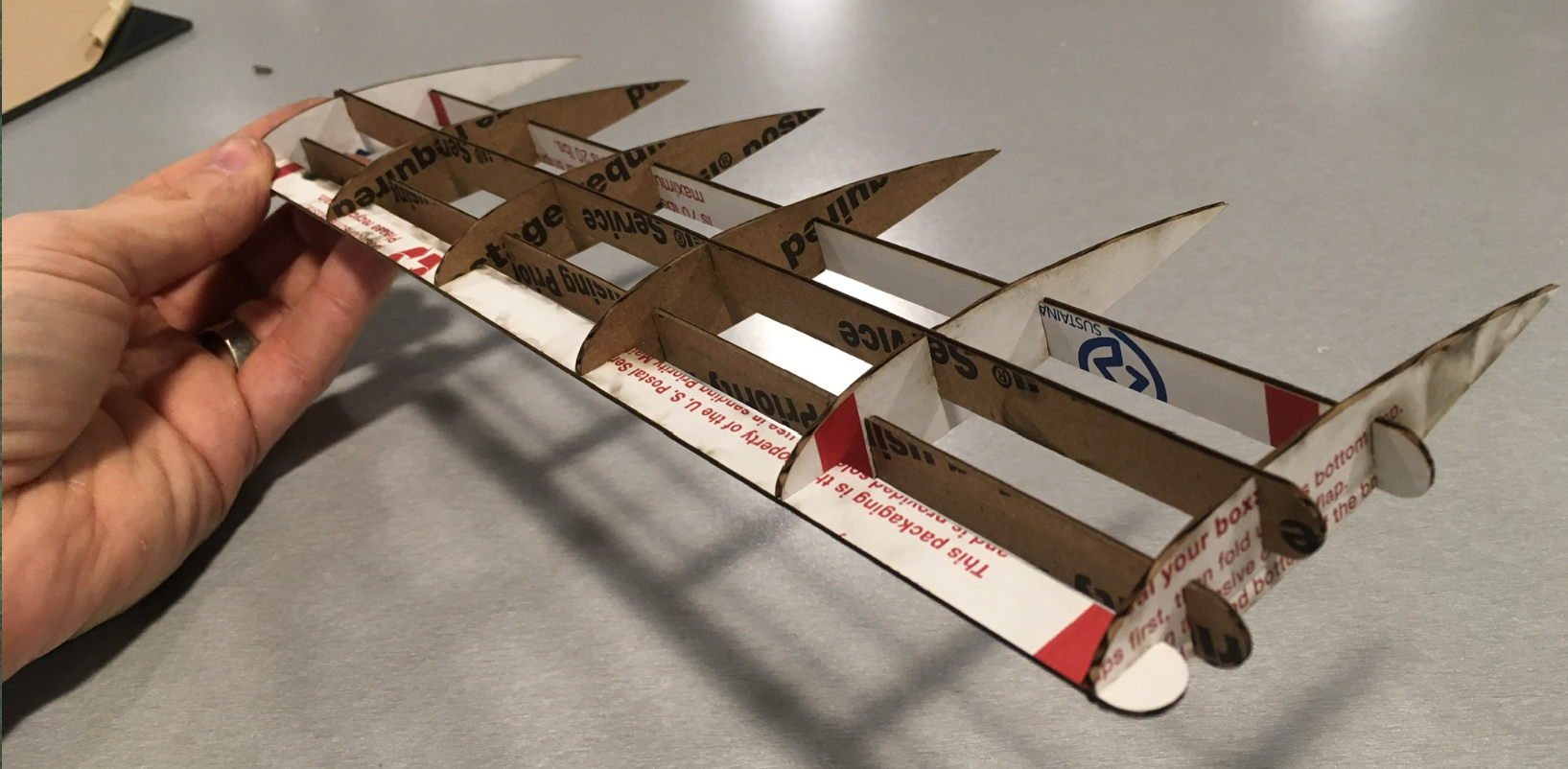
Turned out okay. That's reassuring.
I'm starting to re-think my chord length, though. These airfoils don't fit cleanly on standard FR1.
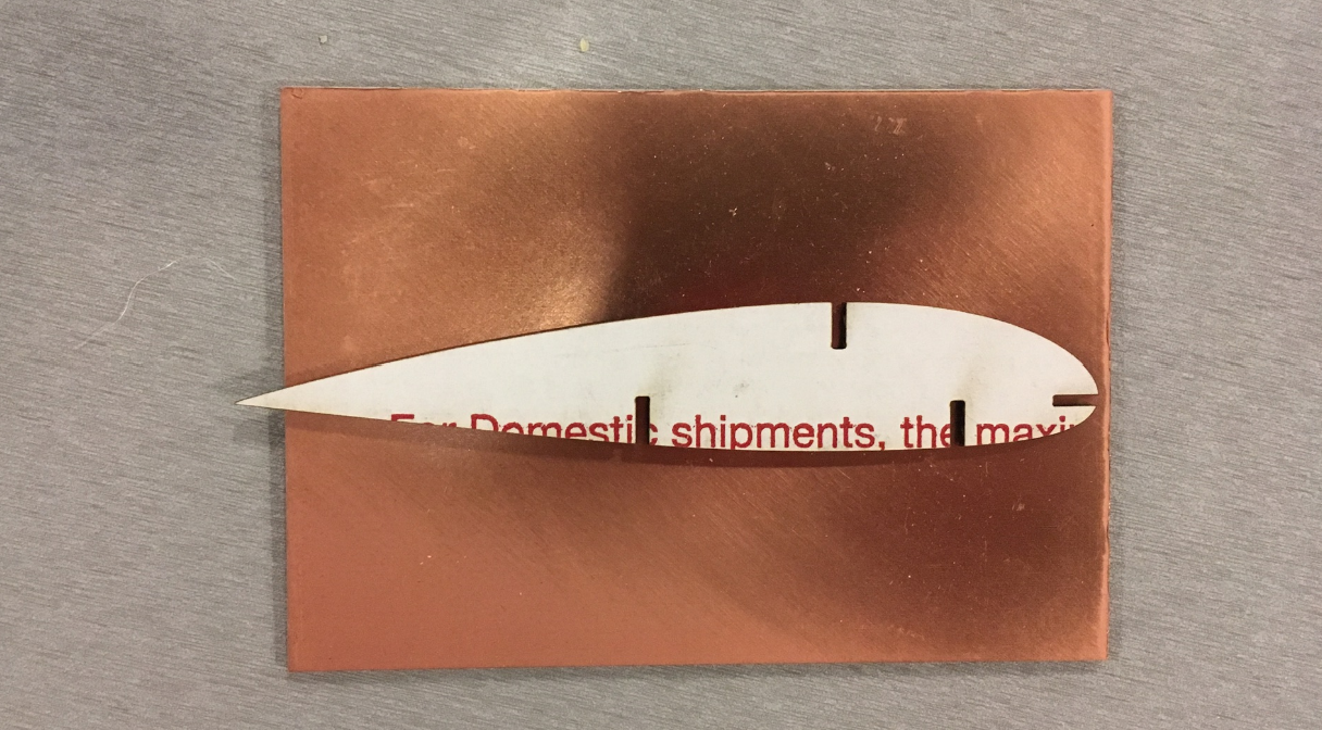
Sure, I could get one airfoil out of FR-1 if I lay it diagonally, but I could get 2 or three if I just shorten it a smidge. On the other hand, I have 20 FR1's with plenty more unused on the "share shelf." So I'll move on to other issues and consider shortening the airfoils later.
First decision is whether to use science fair trifold or some new cardboard I got from an ultrawide PC monitor. At first I was temped to stick with the trifold since I had used in my gauge studies from Assignment 2, but I didn't really record what thickness actually worked (shame on me!). Also, the PC monitor box cardboard is so much stiffer, I can't really turn it down. It's caliper and gauge-making time.
Slot thicknesses and Unit Weirdness Okay, let's think this through. I'm trying to go pure milimeters, but I already kinda cheated with the horizontal stabilizer since the slot widths were already dialed in for USPS cardboard and it was using inches. Now I'm about to make a wing spar that's much thicker than the USPS cardboard, while the wing airfoils are still USPS cardboard. So the thick spar will have thin slots cut into it for accomodating thin airfoils, while the thin airfoils will have thick slots cut into them for accomdating the thick spar.
And Another Thing All slots whether for airfoil or spar, come form the my Grashopper spar generator, which operates in inches. So the path of least resistance is ...
While the path to righteousness would entail ...
I have plenty of other things to modify. Gonna stay on the dark side and set the caliper for inches.
So many thicknesses to choose from. Turns out different parts of that monitor box are different thicknesses. The biggest piece is 0.1570 inches to 0.1805, depending on where you measure and whether you take a "deep bite" with the calipers or only "nibble" with the tips. So given that my gauge generator can make five slots. I'm gonna set the middle caliper slot to 0.1600, and the Slot size to 0.0100 that should give me slots of 0.1400, 0.1500, 0.1600, 0.1700, and 0.1800.
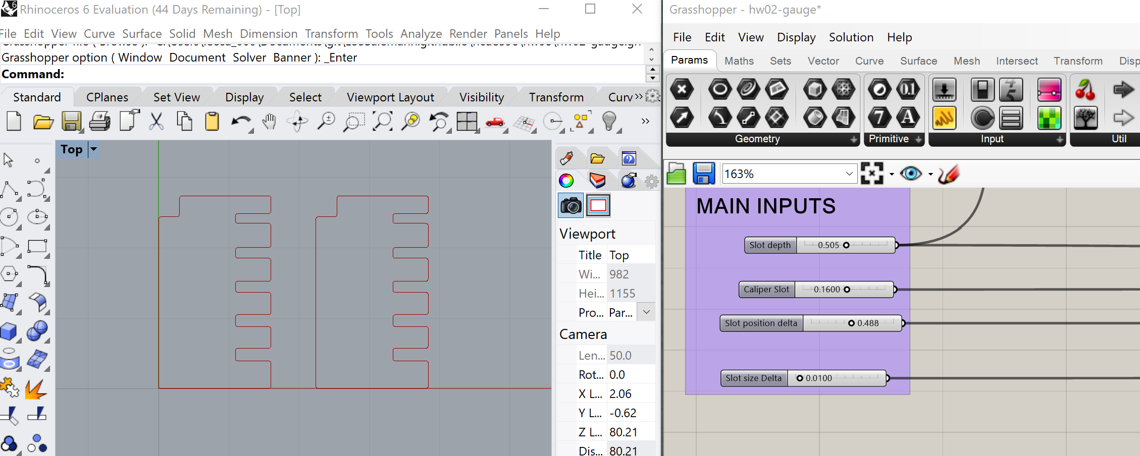
The actual slot thickness is 0.043. I messed up my earlier OnShape extrusions. That's why the airfoil looked so mutch thicker than its "spar slots." Also the UWB Mill is closing and I have to leave
Had a few thoughts on the drive home.
Getting ready to buy stock parts and Acrylic, before reaching the MILL by 1pm. Copy/paste my parts Measurements from prior days:
All right, time to shop!
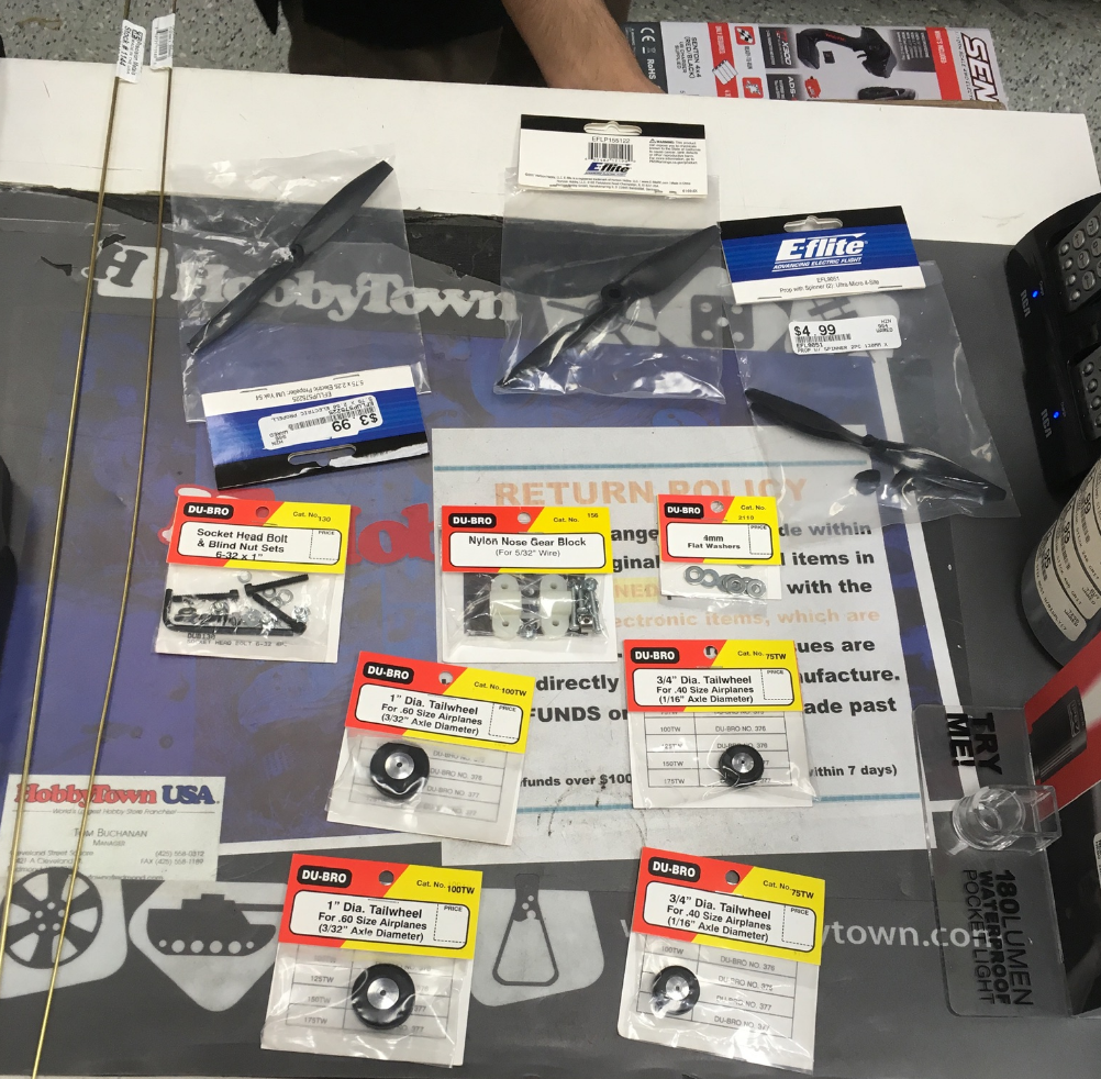
Lots of variables to consider with wheels. Wheel diameter, axle diameter, meltal rod (axle) avaialability, and what fits into the 3D-printed slot from my Assignment 3 "lamp legs." Grab a bunch of wheels, walk over to the metal wire selection to find an axle. Found a brass hollow tube at 1/16 inch diameter, matches one of the one of the wheels I found, snugly fits into then 3D printed struts I brought with me. Some wheels mark their axle size in fractional inches, some in decimal inches, some in millimeters. Delightful. Google tells me 1/16 inch = 0.0625 inch = 1.588 millimeters. No other wheels in my favoorite axle size. Going to buy 3/32 axle and wheel as well, so have the possibility of tricycle gear. I should be able to crush the 3/32 axle to fit the 3D-printed slot.
Also bought a couple props and mounting hardware.
This should be straightforward, I know what I need and how big it should be. Minor hiccup, they gave me extruded acrylic instead of cast, which was covered in plastic film instead of paper tape looking stuff. I was worried about the horror stories of uneven thickness, so I asked for a cast piece instead and TAP was awesome. They took the extruded one back even after being cut, and all I had to do was pay the difference for the cast piece.
Now, about that gauge ... Laser cutter queue is mutiple people deep. Catch up on documentation, and plan what's next.
A cunning plan for landing gear integration. The landing gear is going to re-use the struts I made in Assignment 3 , they'll just be shorter and have a slot at each end. The key thing is, the wing spars will be thick PC monitor cardboard wile the landing gear attaches to thin USPS cardboard. So, I'm going to have to make a "secondary spar" of USPS cardboard for the landing gear to clip on to. The key point here is for this spar to be slotless so I don't have to worry about perfectly aligning slots between to different spar lenghts and cardboard types. Time to open up Rhino and CAD something up.
Copy one of the slots from the horizontal stabilizer airfoil, copy to the main wing airfoil. Hand-build a rectangle that matches the dimentions of the horizontal stabilizer.
WE INTERRUPT THIS CAD SESSION FOR SOME LASER CUTTING My slot opened up in the queue, time to go. Load up the PC Monitor cardboard, key in my favorite settings.
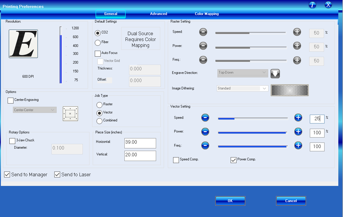
Aaand ... it failed to cut through.
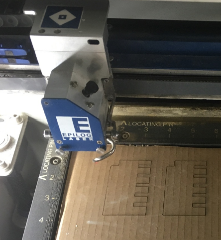
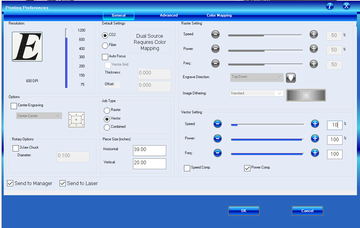
Set the speed down to 10% and try again.
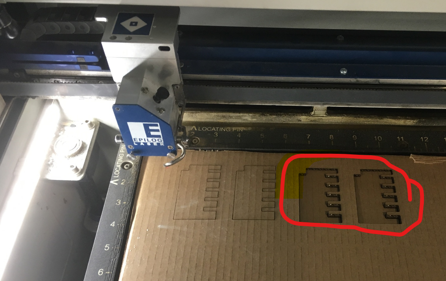
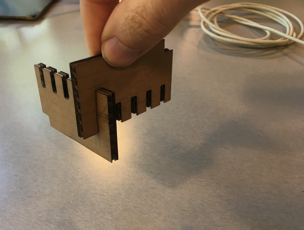
Curious. Usually it's the smaller gaps that fit best, but this time it was the biggest. No matter, I'll take it. It's a good snug fit.
Pivot Back to Inches(?) Airfoil was in millimeters, gauge generator's in inches, spar generator's in inches. Really shoulda spent some time converging to mm, but the path of least resistance (cringe) is to convert my rhino document to inches. Save a copy of try04 as try05.
The deed is done. Now I should be able to make a 12.0 by 0.5 inch rectangle for the "landing gear spar" Then make a 0.5 by 0.043 inch airfoil slot. It worked, but I don't like how deep it's cutting into the airfoil.
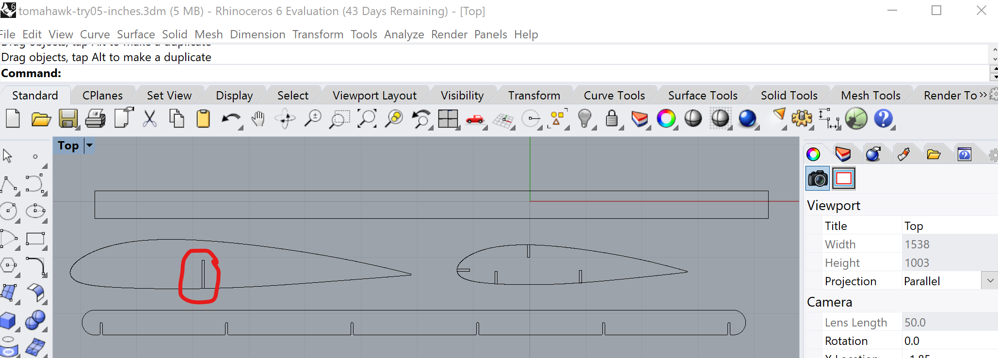
Let's freehand an airfoil slot rectangle, to dial in the "airfoil depth." Here's a good depth - 0.45 inches. Works for about the first third of the chord lenth.
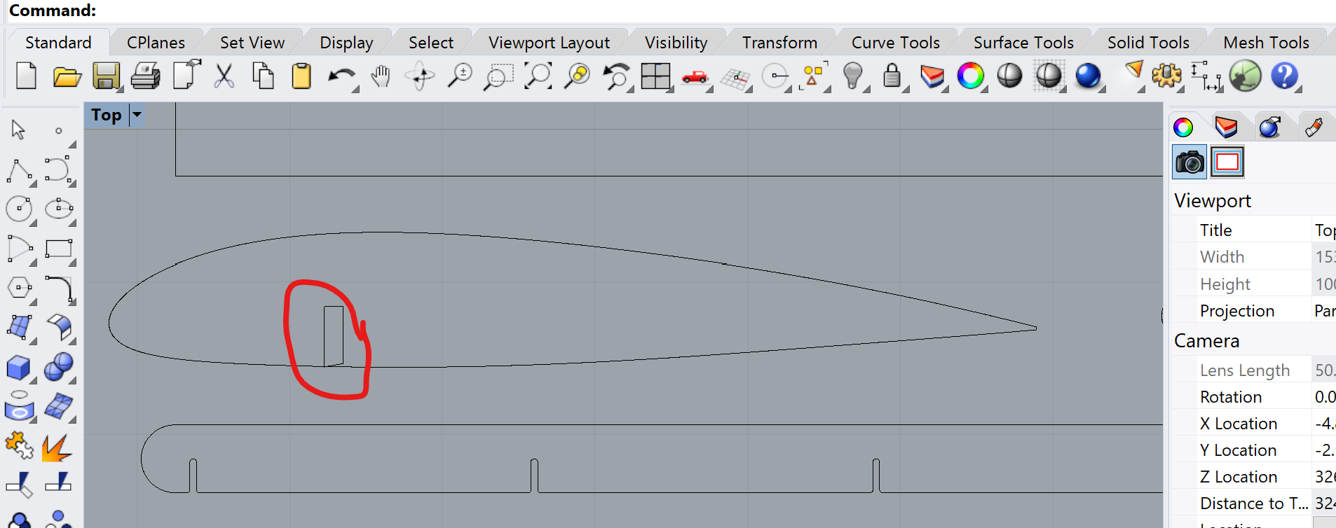
New Rectangles. Now I should be able to make a 12.0 by 0.45 inch rectangle for the "landing gear spar" Then make a 0.45 by 0.043 inch airfoil slot. In another attempt to be clever, I'm going to have a forward "landing gear spar" for tail-dragger (big wheels in front) as well as a 45-degree canted spar for tricycle-style (big wheels in back).

Now let's generate those airfoil slots
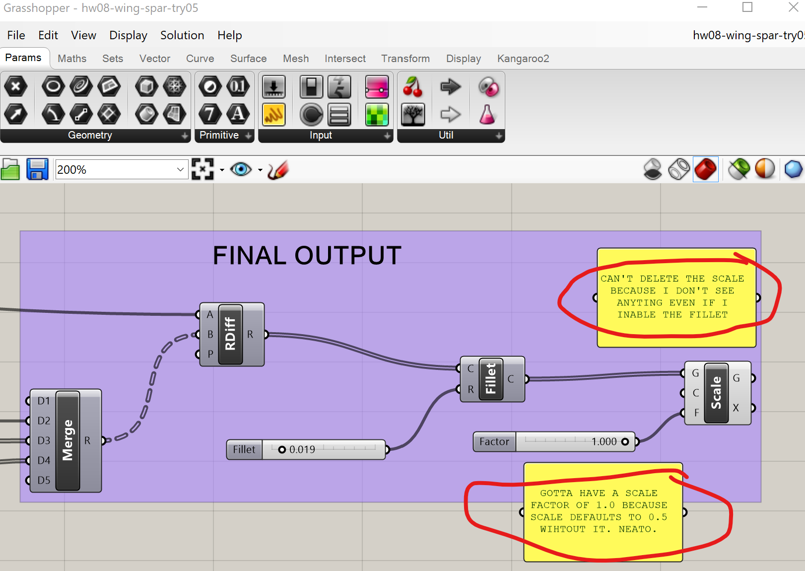
Aaand ... dinner break.
Ok, we've got all the wing components in Rhino, let's migrate to Adobe Illusrator and prep for lasercutting. Rhino seems to resent the unit conversion as much as I do, and has decided to make things difficult when I export curves from Rhino to Adobe Illustrator. Gotta twiddle the knobs and find what works.
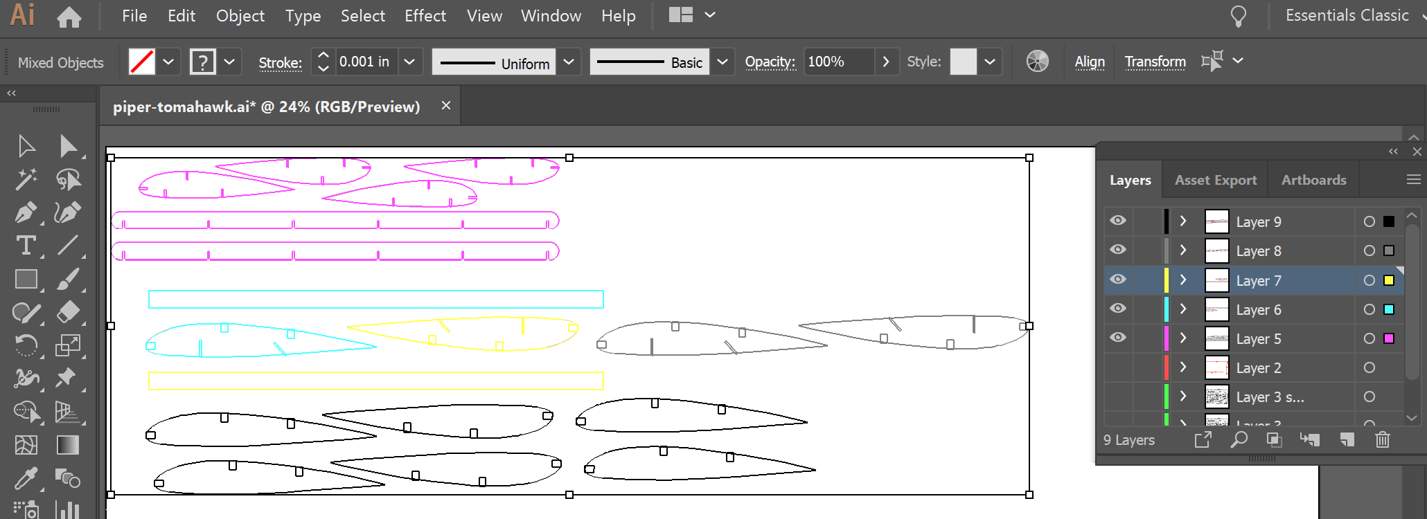
Ok, we've got one of each major part in Illustrator - wing spar, wing airfoil, and landing gear spar. Now that we're in Illustrator, we'll group, copy, and paste to make multiples and lay them out in a way that's optimal to the material we're cutting and what's been cut before on it. After multiple rounds of copy, paste, and transform; my layout for the next USPS session looks like this (below.) I've also segregated groups into layers, so I can cut a few pieces, confirm the fit, then cut the rest.
Okay, let's cut! Start with thick PC Monitor cardboard,cut a wing spar. Turns out 10% speed was too fast for some parts of the spar, but it can still be punched out. Switch to USPS cardboard to print an initial foil and landing gear spar.
Turn the speed back up to 25%. USPS parts cut fine (though I forgot to refocus the laser - oops.) The initial test fit (one main spar, one airfoil, one landing gear spar) checks out, so print the rest of the USPS parts. While that's cutting, jump back to the Ilustrator file for the main wing spar and make two more (shame on me for not doing that before approaching the printer). No matter, the new file was ready before the USPS parts finished cutting.
Reload the PC Monitor cardboard. Drop the speed to 8% this time, cut two more spars. Much better. Put it all together and ...
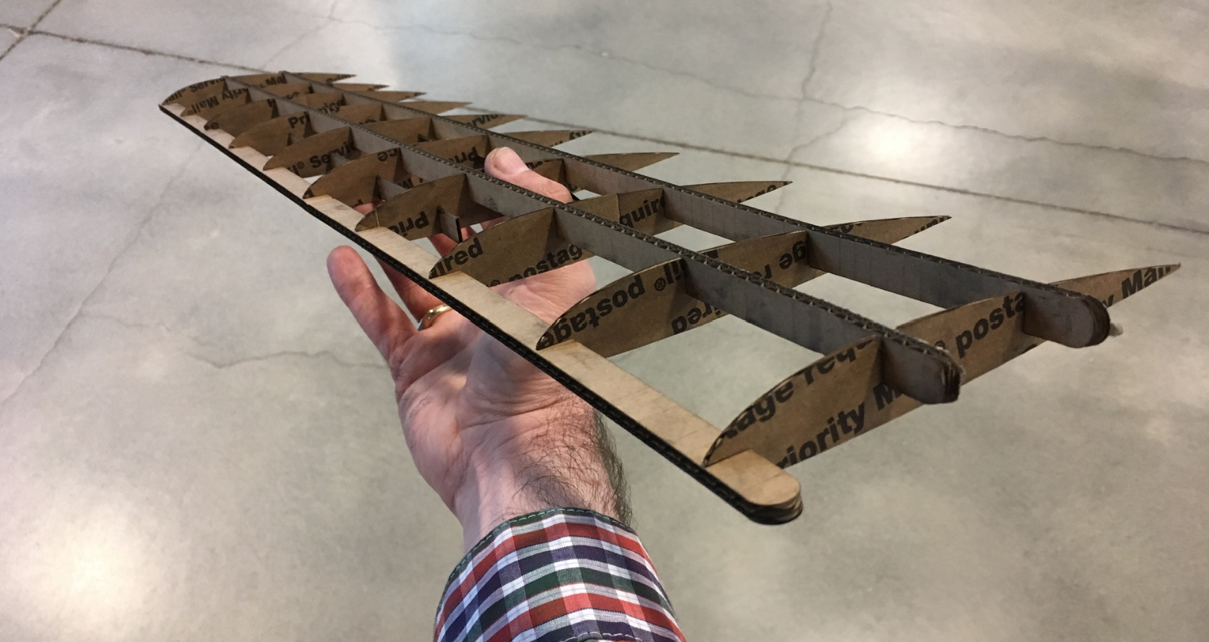
Okay, it works and passes the shake test. Fairly happy with the fit, but if I have time to cut another (yeah, right) I'll increase the main spar height, and cut the airfoil slots a little deeper on the leading edge.
The final fuselage will be in acrylic, but the first cut(s) will be in cardboard. The whole reason I chose a piper Tomahawk is because the wing attaches right to the bottom of the fuselage and the horizontal stabilizer attaches right to the top of the tail. So the top of the tail will need to be shaped kinda like half an airfoil, and have USPS-sized slots cut in it, ready to receive the spars from the horizontal stabilizer.
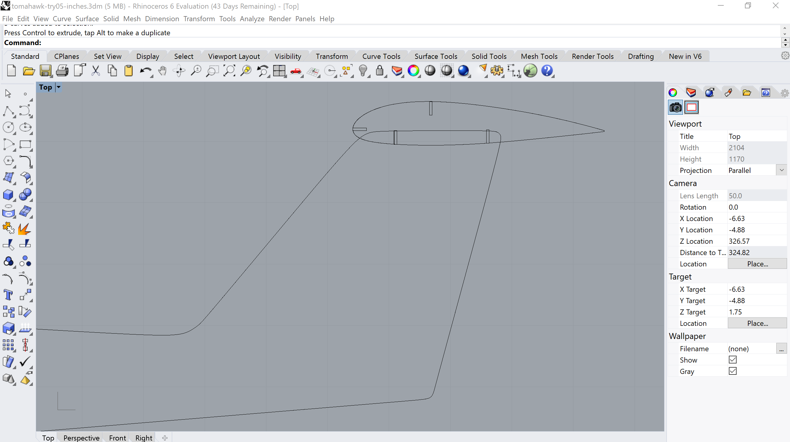
The main wing's going to be trickier. I'm going to need to reshape the bottom of the fuselage.
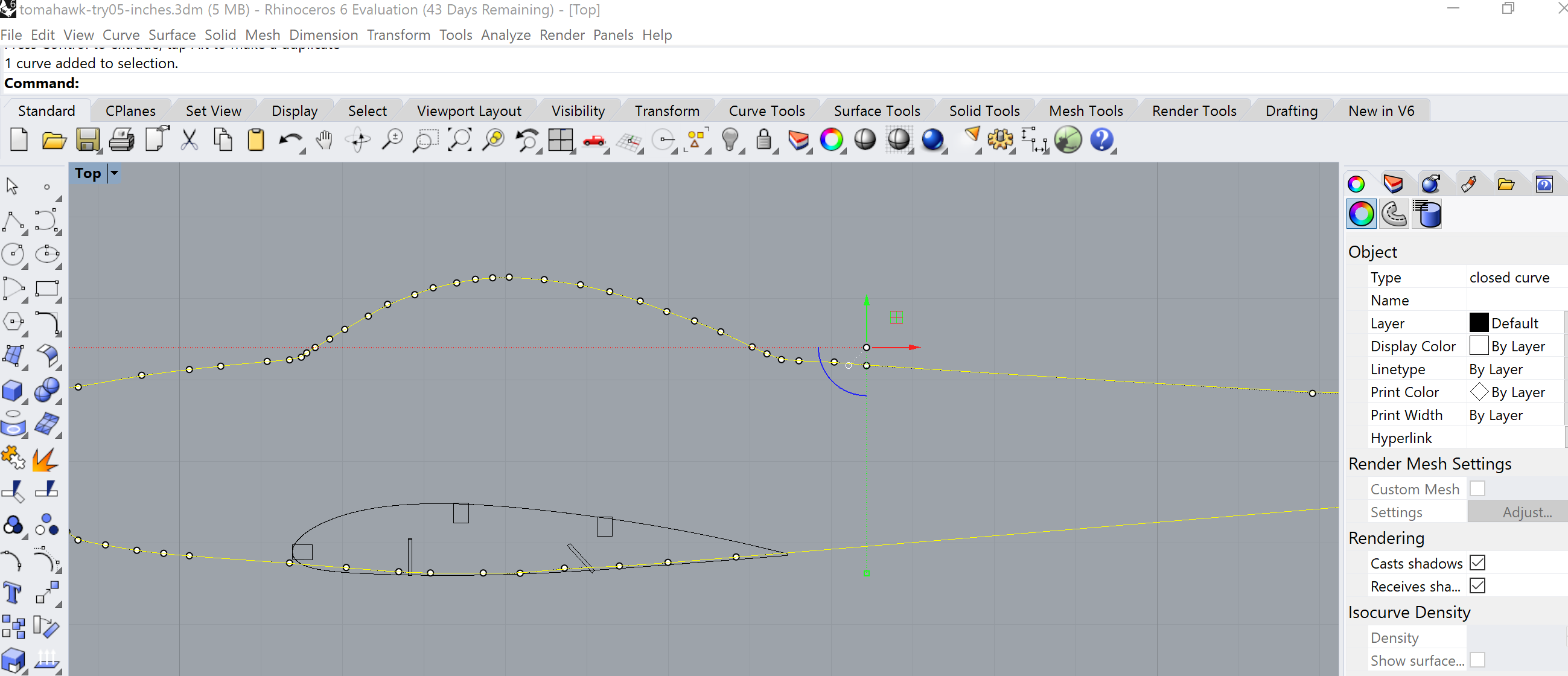
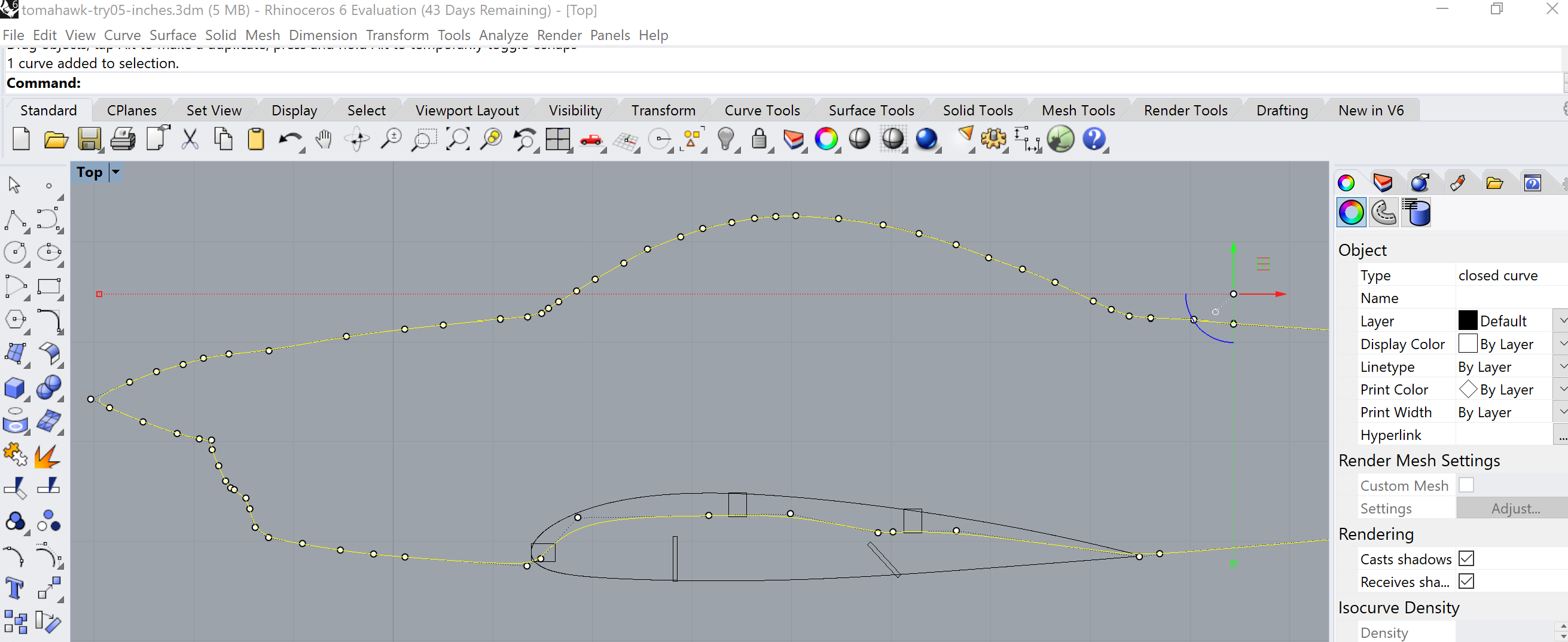
Prep the Fuselage Make copies of the airfoils and move them away from the fuselage to keep them safe. For the ones still touching the fuselage, ungroup the airfoil from their various spar cutouts. Delete the foils and uncessary cutouts, so only the slots relevant to the fuselage remain.

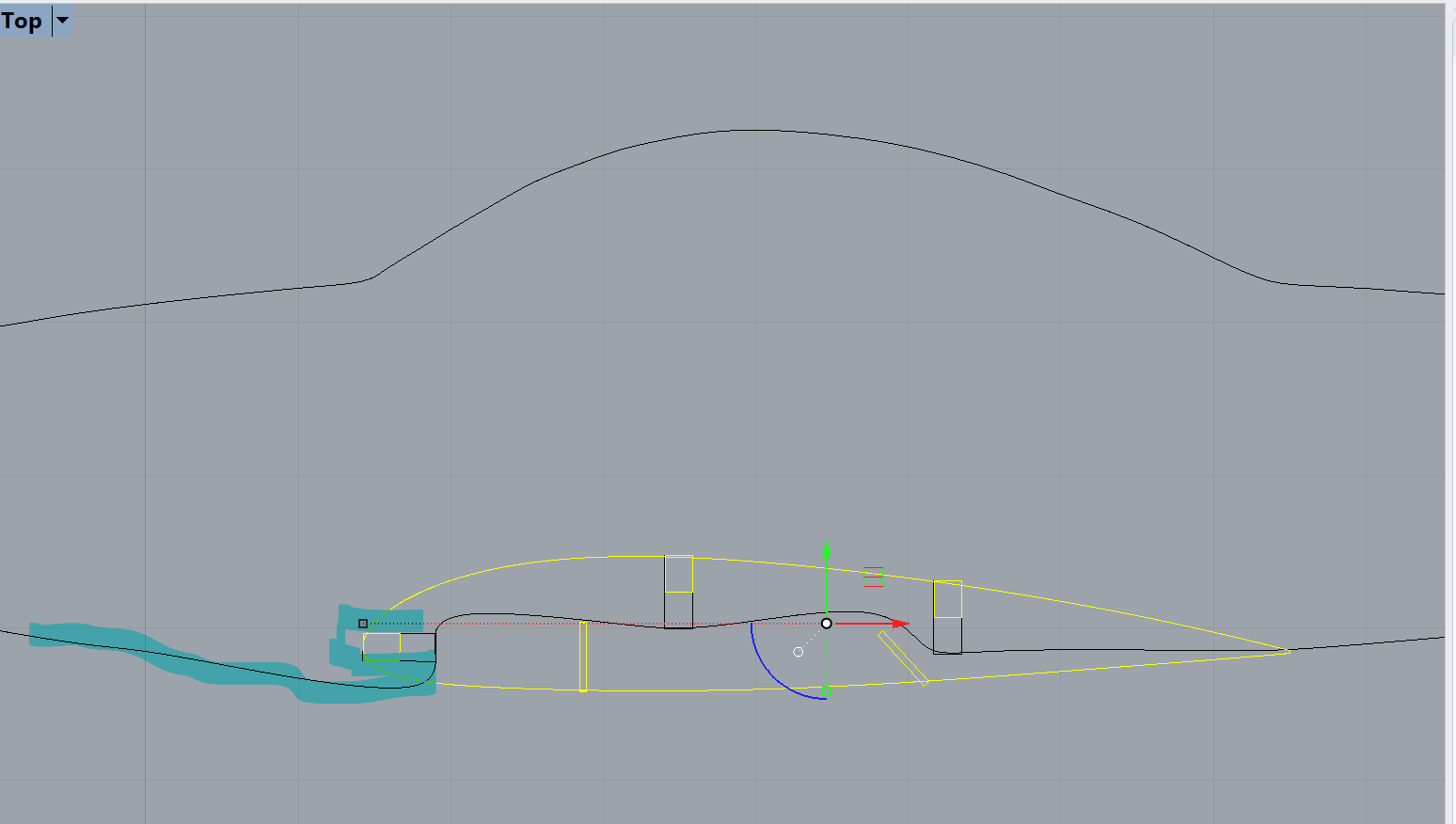
Crap. The fuselage slots need to be twice as deep It's the same story as the extra-deep slots for the smooth landing gear spars. Back to Rhino, line up the tail again.

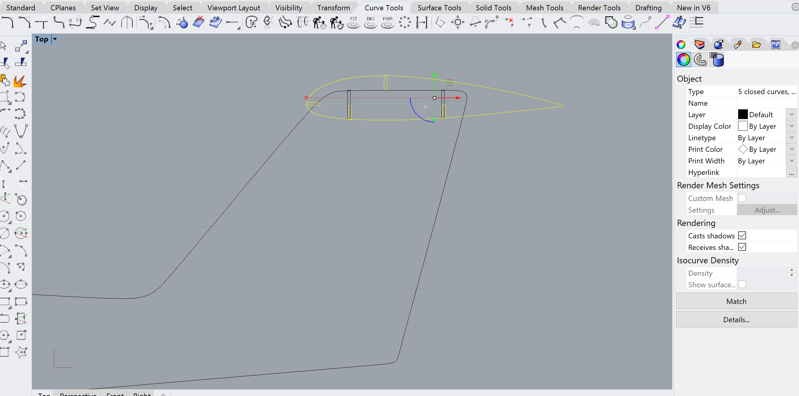
The Trick is to use Rhinos Scale1D command while enabling point in the OnSnap tab at the bottom. Click one corner of the rectangular slot for the base point, then the next point in the direction you want to scale.
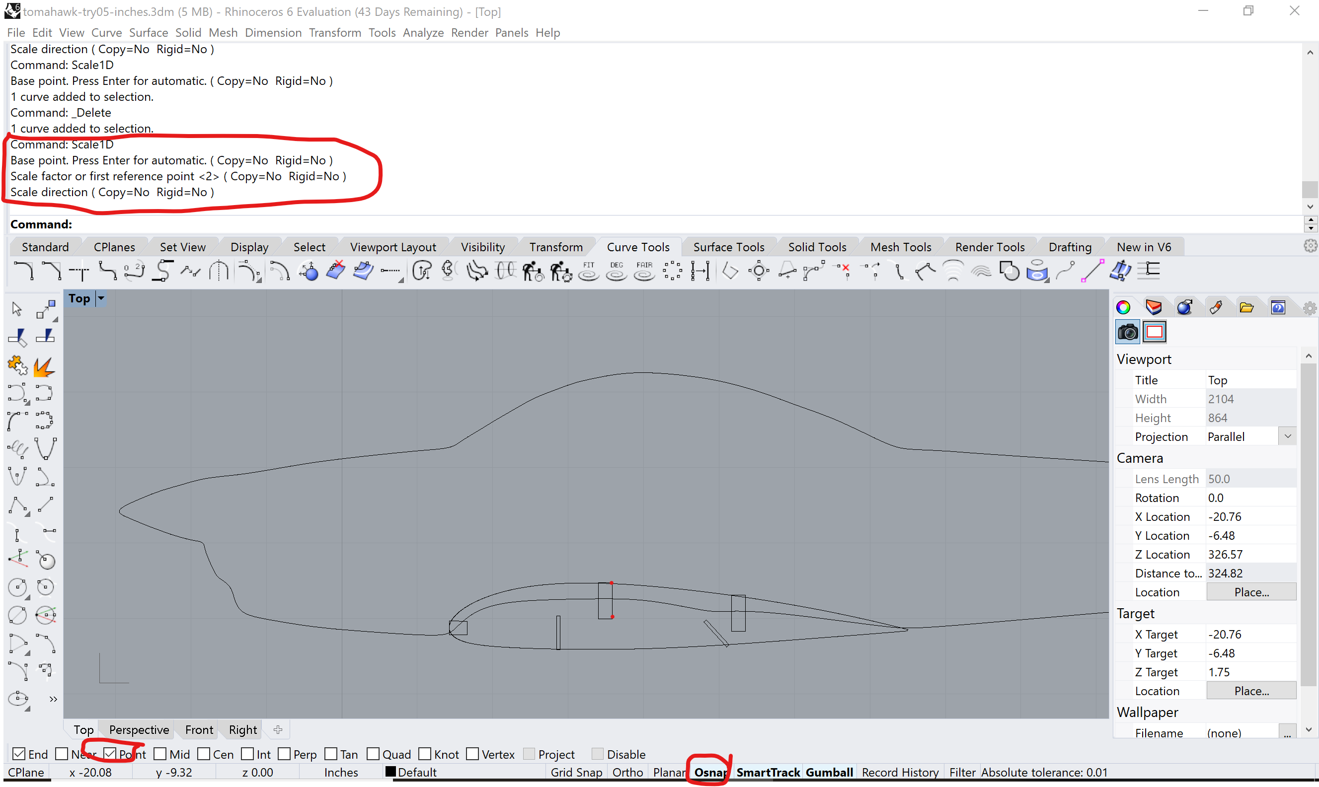
A little more Scale1D voodo gets you a main wing integraiton like this.
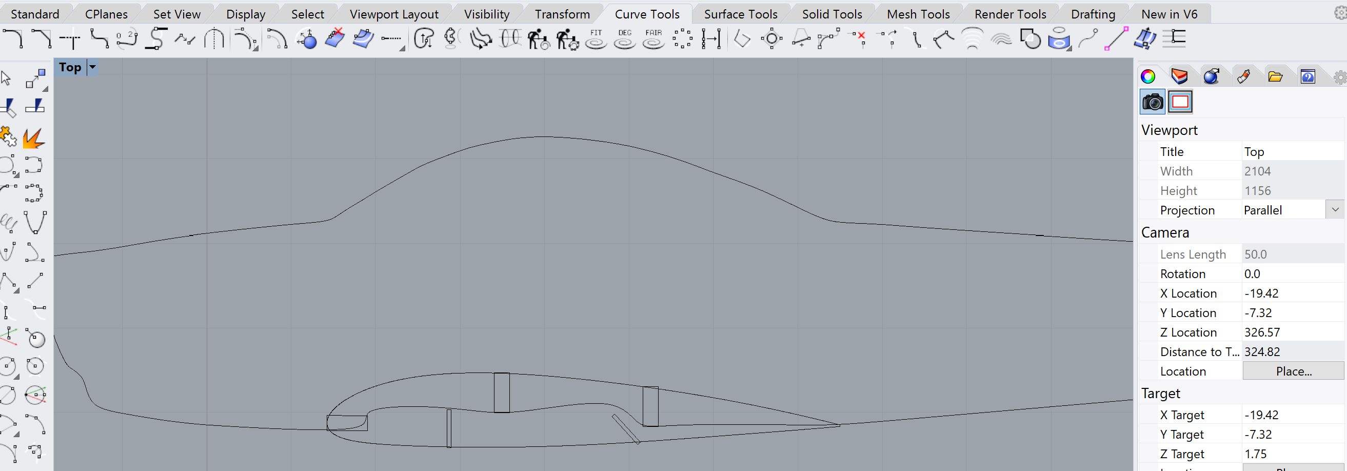
Which looks like this without the actual airfoil.
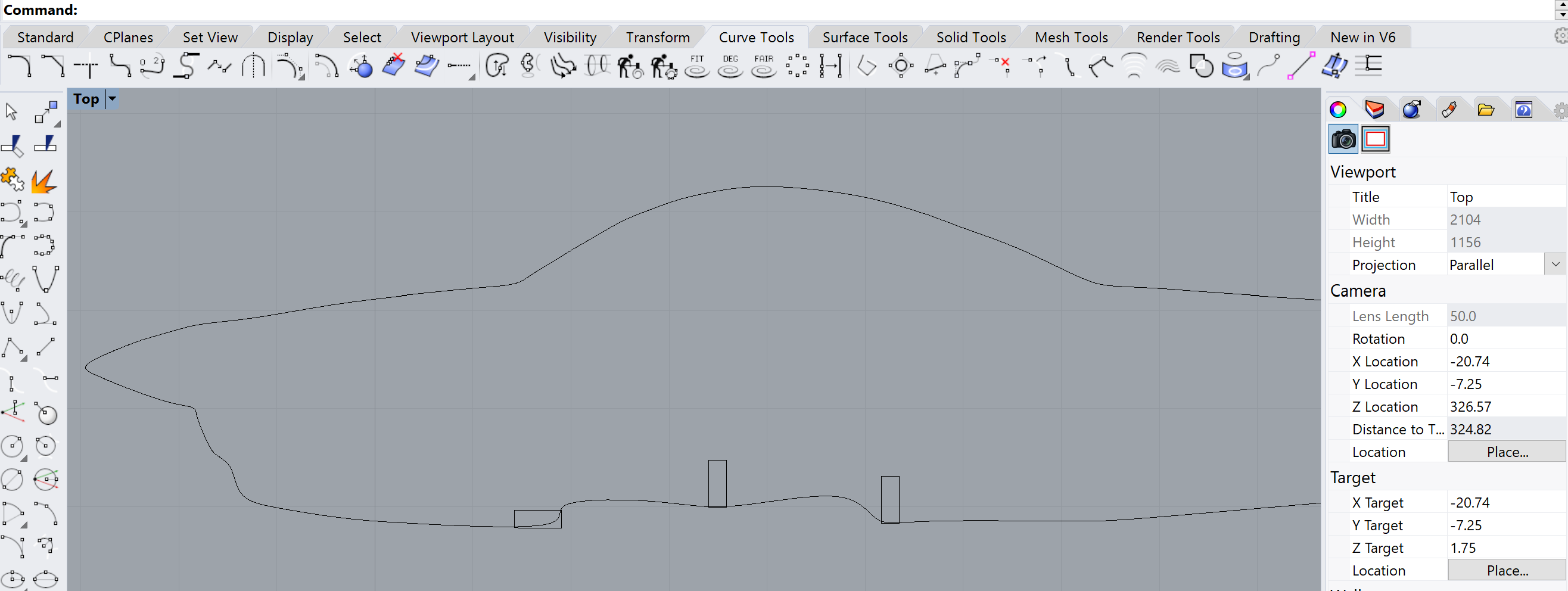
Now, we can import the fuselage into Ilustrator. Use DXF, fight with units and scaling until it looks right.
Ok, so for real now; which cardboard? I'm not ready to use prime PC monitor cardboard on this yet, and I'm pretty convinced the material thickness won't matter. So I'll start with science fair trifold and work up from there.
Fine then, let's print. Started with the small hunk of trifold cardboard, normal Epilog settings, speed 25%. Nope, way too small. Good thing we did a practice run with red dot and the Epilog open. Swap with the larger cardboard (had to trim it down to 32 inches) Laser head moved unusually slow, but it worked.

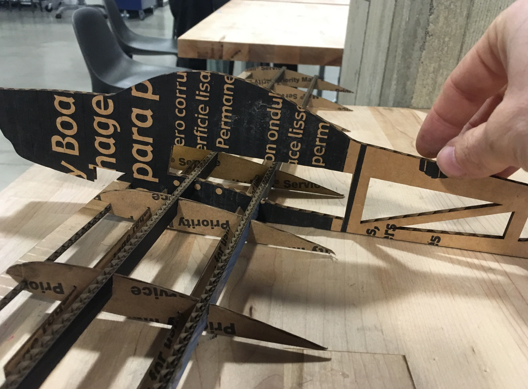
Assembly was ... ok. It passes a gentle shake test.
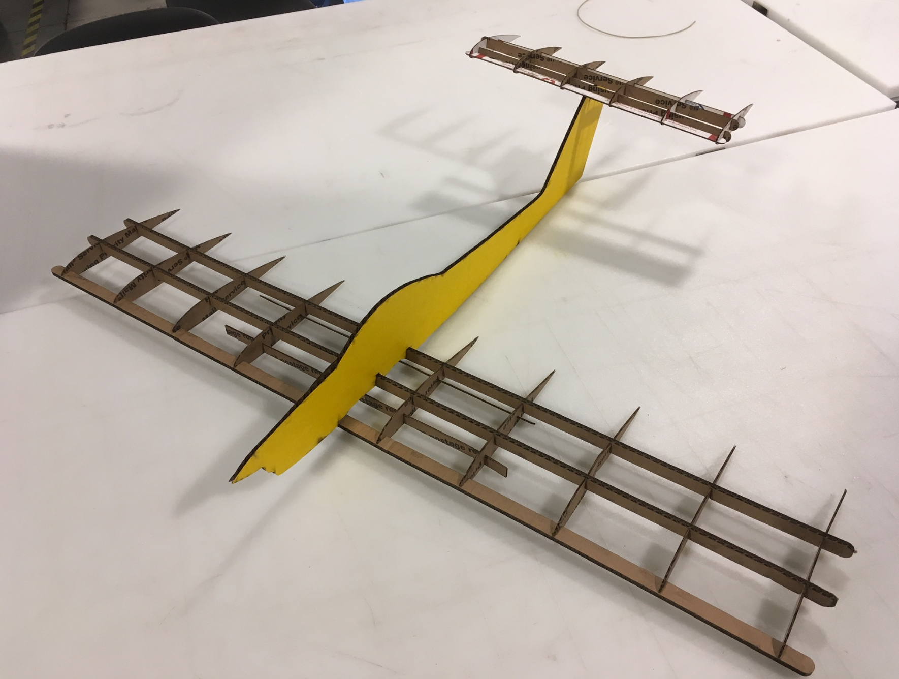
The biggest fit-issue is the horizontal stabilzer. I didn't cut the same "front notch" as I did for the main wing, so it doesn't fully settle into its slots.
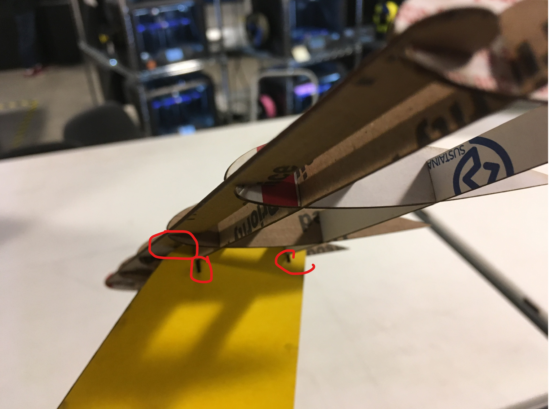
The fuselage could use a few tweaks to get the wing and horizontal stabilizer to fit better. It would be good to start Sunday's session with some landing gear struts that are ready for 3D printing. Fowler flaps are off the table, but some CNC parts are a possiblity for moving alierons and elevator. Also found an opportunity to use OnShape to cut some holes for mounting a propller bracket. Okay, how can I sequence these so they make sense?
Okay, no matter how I look at this, prepping for 3D pringing's the right thing to do at this time.
10:58PM About those Struts... Reach back into the hw03 folder Thank goodness I made a README file. Looks like strut.3dm is the file I want. Copy it over to hw08 so I can have my way with it. Pretty basic job. I just have to shorten it and replace the T with another notch.

But how long should the struts be? Time for a prop-clearance study. Reach into the HobbyTown Goody Bag. Pull out a prop and some mounting hardware. Insult a small phillips screwdriver by using it to punch holes into my cardoard fuselage.
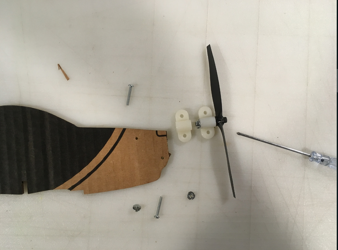
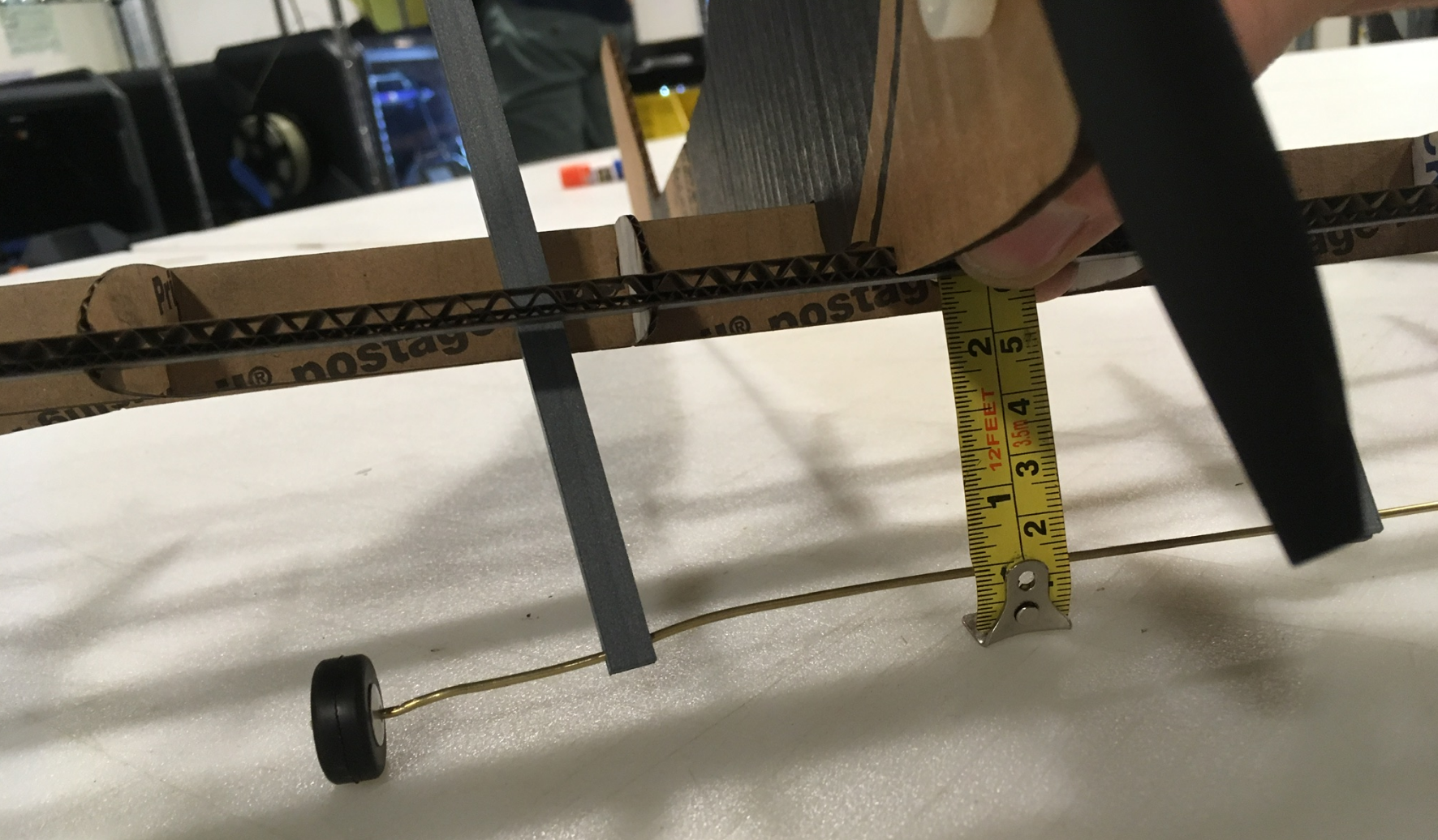
Rig up some Landing Gear Back to the HobbyTown Grab Bag, pull out some small landing gear wheels and the 1/16 inch hollow brass axle. A little soft and bendy, but works pretty good. Pinching on either side of the wheel keeps it from sliding up and down the axle, but pinching to close binds up the wheel so it can't roll. At least my plane will be able to taxi in circles. Most importantly, the Assignment 3 struts fit as expected.
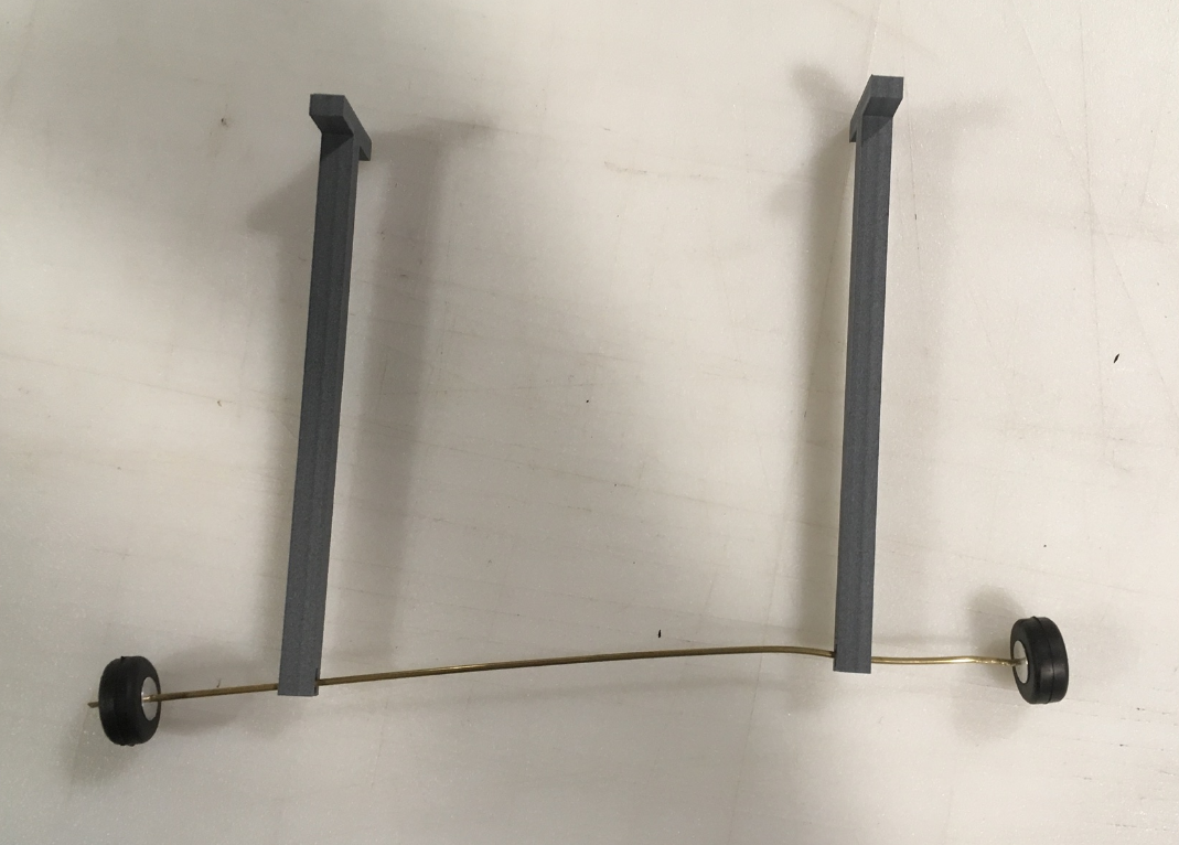
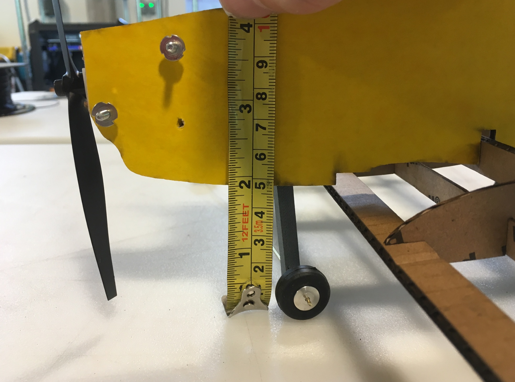
Ehh... 60mm looks right. Airplane looks good as a Taildragger if it’s 60 mm from leading edge to axle. This comes out to about 60 mm overall when you account for the extra length to accommodate the slot, the position of the landing gear spar, etc. Pretty sure this will work for tricycle gear too.
I'm awake, I'm alert, let's cad up the landing gear. Needs to be 60mm long, with a notch at both ends. Open a copy of the assigment 3's "T-strut," in Rhino; delete the polysurfaces, keep the curves. Use the Rectangle command to just build a new rectangle copying the height of previous and setting length explictly to 60mm.

Extrude the new curve. Go back to Assignment 3 to find the extrusion height from last time. Crap, I didn't record it. Guess I'll just eyeball it (again). Exrude the "slot piece" but make it a bit taller to make sure it cuts all the way through when I do a boolean difference. Slide it down in Z a little for similar reasons. Copy/paste, and move the second slot piece to the other end.
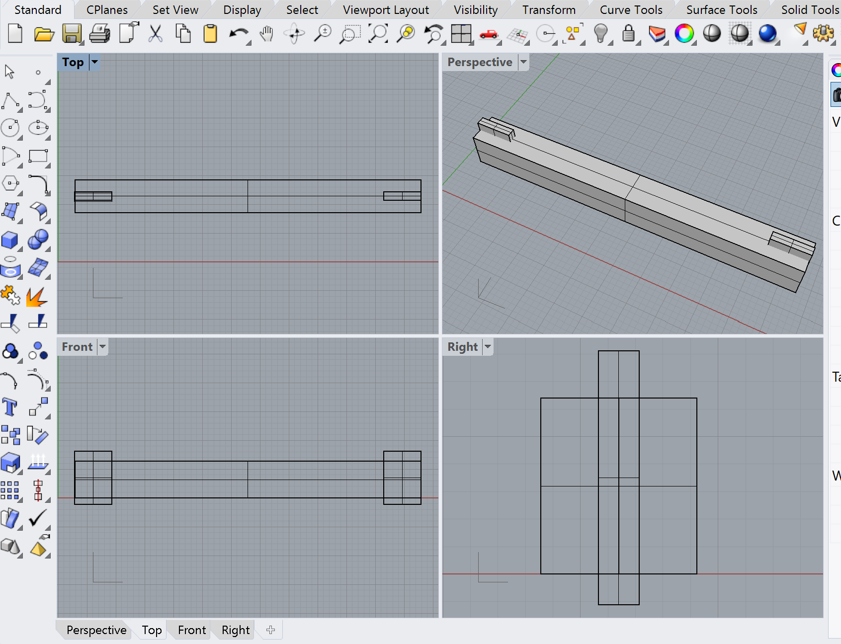
Do the diffs, ready for Dremel. Let's see if Assignment 3 can help me with that.
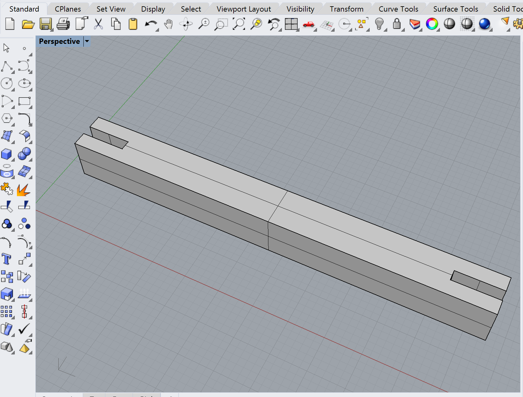
Okay, not too bad. Export to STL; default options. Pull into Dremel DigiLab; check sizing. It's 60mm long on the first try? How did that happen?

Pull in a second one, generate g-code Layers look legit. I think I'm ready to print, and it's only 10:30am!
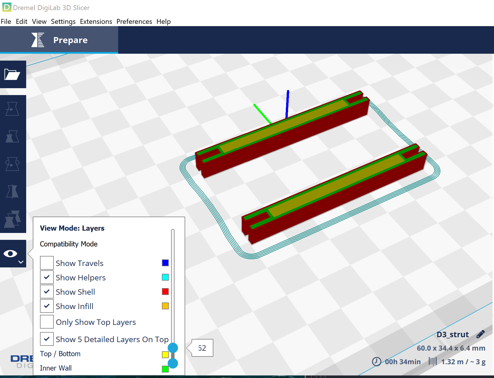
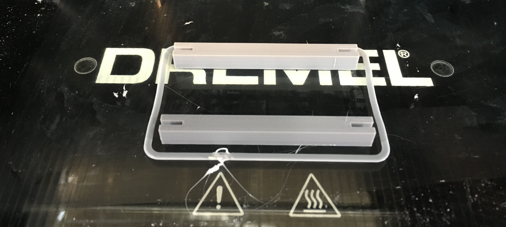
Grabbed a Dremel Digilab from the top shelf (I think they get used frequently) and got my 3D print underway. Use the Dremel DigiLab Printer Settings from Assignment 3 Looks like it'll be a half-hour. Just-enough time to clean up some doucmentation from last night. Aaand I got something!
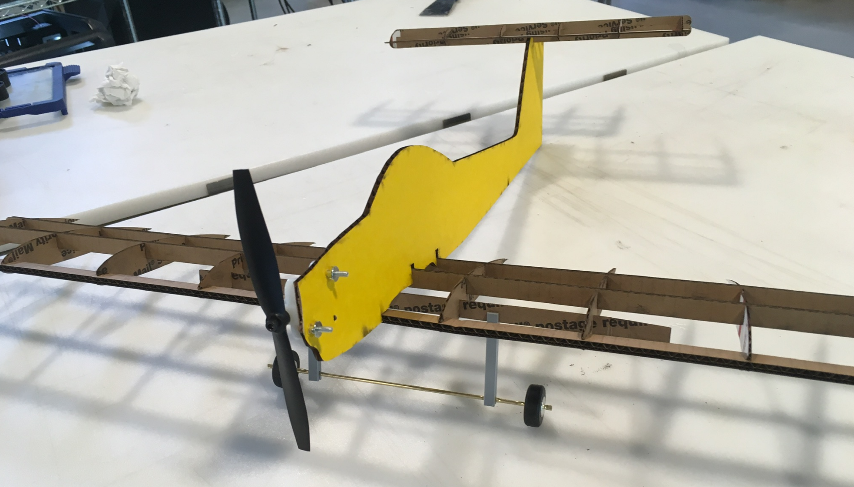
Looks as expected as a tail-dragger.
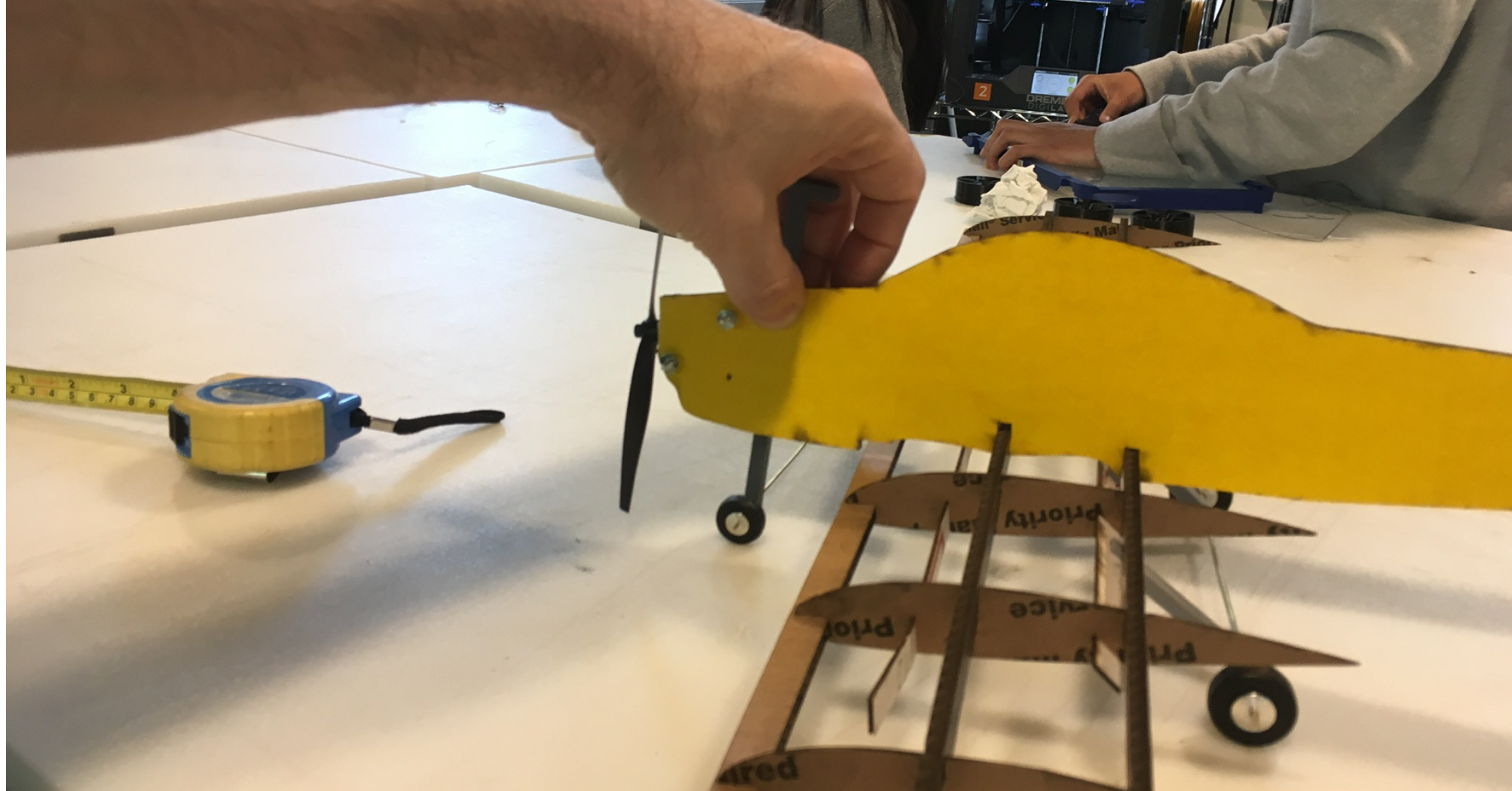
Tricycle gear setup works too. Wheel's are far enough aft to ensure the plane will rest on its nosewheel.
Looks like 60mm would work for the nosewheel too, though the slot for the fuselage would be every different.
Now About That fuselage ... What I have now is waayyy to loosey-goosey. There's a couple ways to fix this.
Ok. I have an idea for a simple elevator hing that will hopefully work. Take the airfoil I have, and use a pair of "half circles to " cut it.
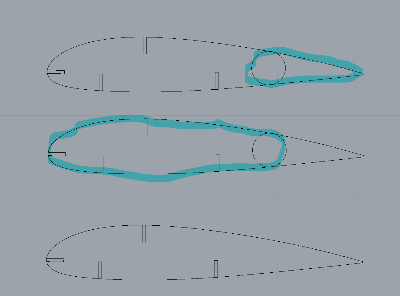
Put a hole in the middle of the center for one of my McMaster-Carr rivets, and I'm set. Every elevator airfoil gets replaced with this pair. Add a regular horizontal stabilizer spar to the trailing edge (not leading!) of the elevator to hold things together. Prototype in cardboard; final in CNC (hopefully). Ironically, I can probalby test on CNC before a slot opens up on the laser printer. We'll see. Meanwhile, off to the McMaster-Carr grab bag and my caliper.
Turns out I had a couple extra airfoils, so I could do some low-fi prototyping. With an exacto knife. Both the click-lock(left) and arrow(right) shanks work and look reasonably good.
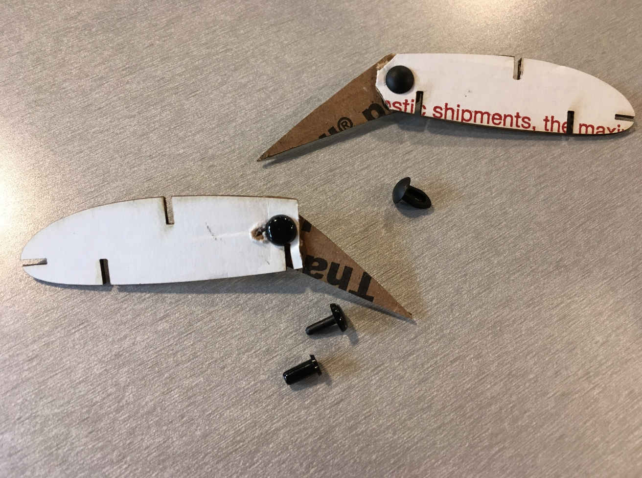
All things considered, I'm favoring the arrow shank, since I believe it will be more forgiving in terms of hole size. Bigger holes are easier to measure accurately, and the click-lock shanks just look like they demand a perfectly-sized hole to keep from wobbling and rattling, while the arrow shank is meant to "squish down" if necessary. So what steps lay ahead?
Rhino to DXF to OnShape I tried trimming in Rhino, but that function always cuts something I want it to keep. Turns out I dind't need it. I can import the dxf using the top menu option not the bottom. Extrude by 1.5 mm (just as a test) and I've got just what I was hoping for.
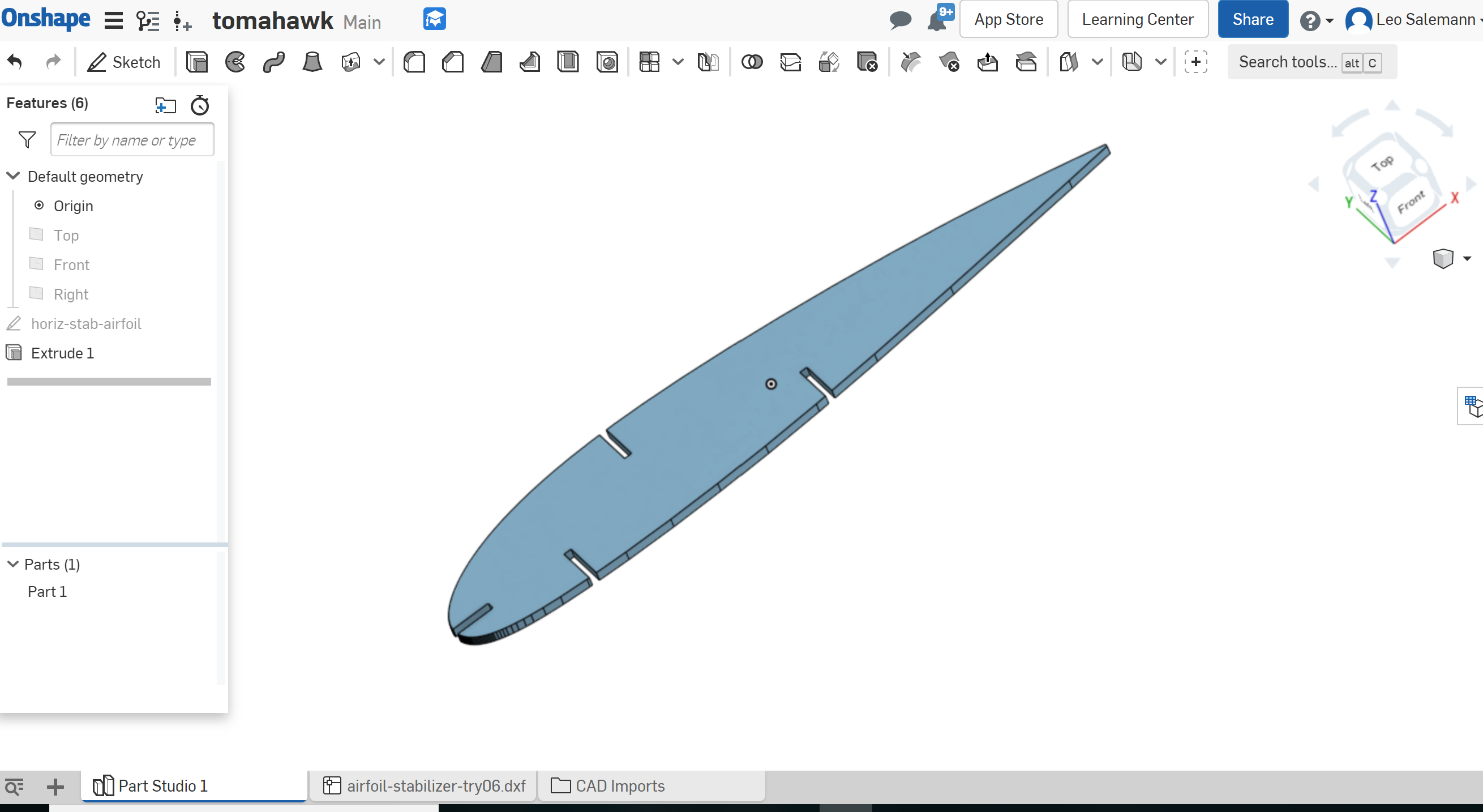
All right, let's see if we can cut this thing with a couple half-circles. Start with a copy of the sketch, working in 2D. Make some construction lines.
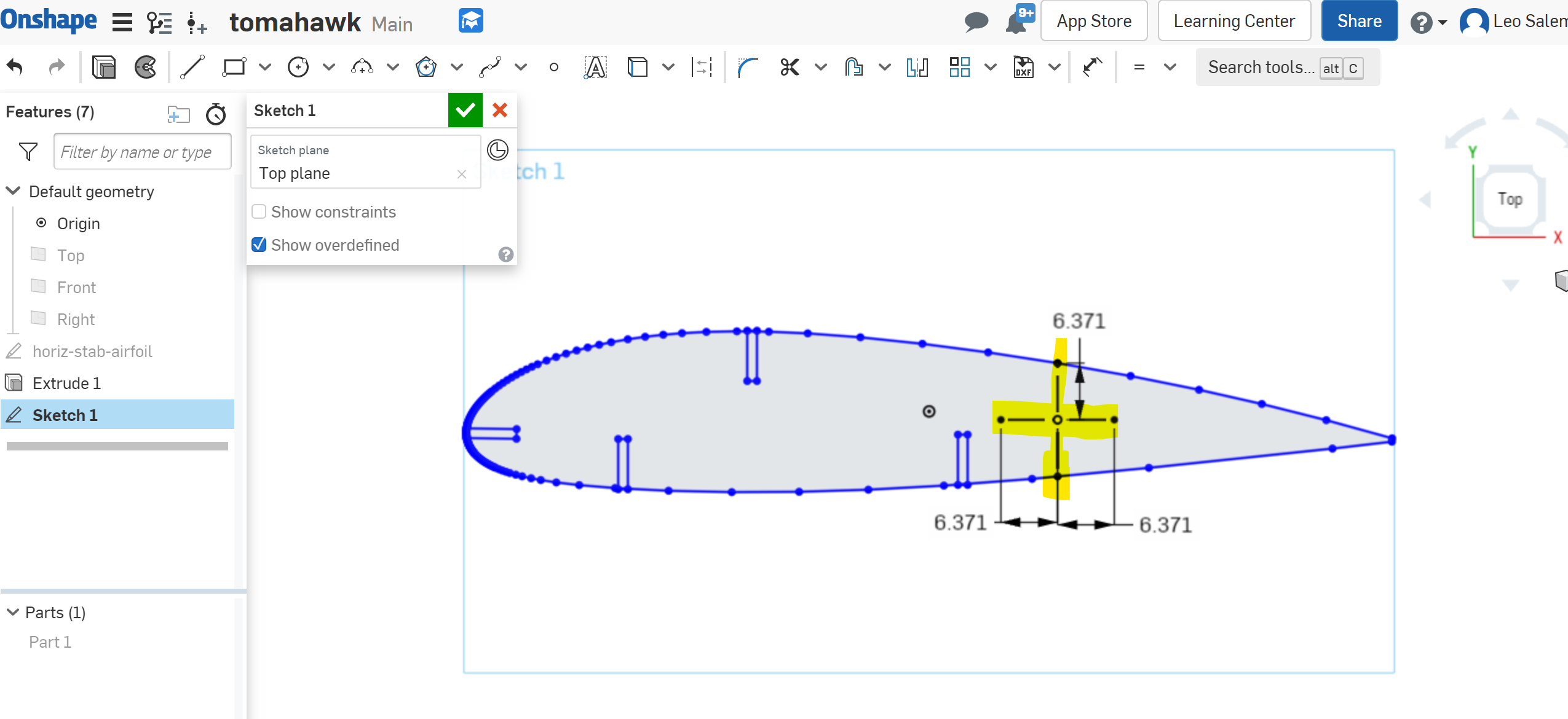
Next make those three-point arcs.
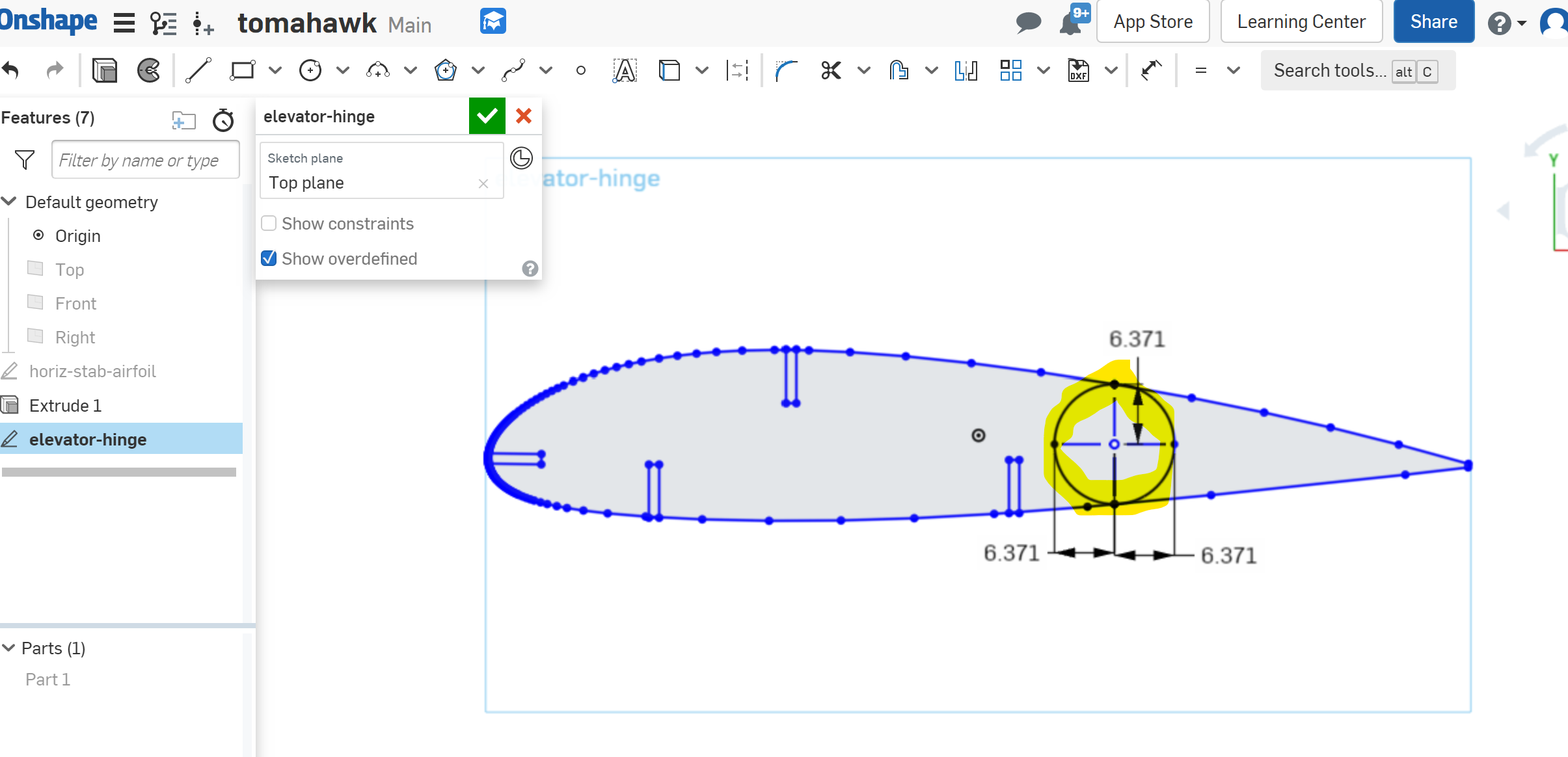
Now a couple strategic extrusions, by 1.53 mm (USPS thickness). Huh, it worksd.
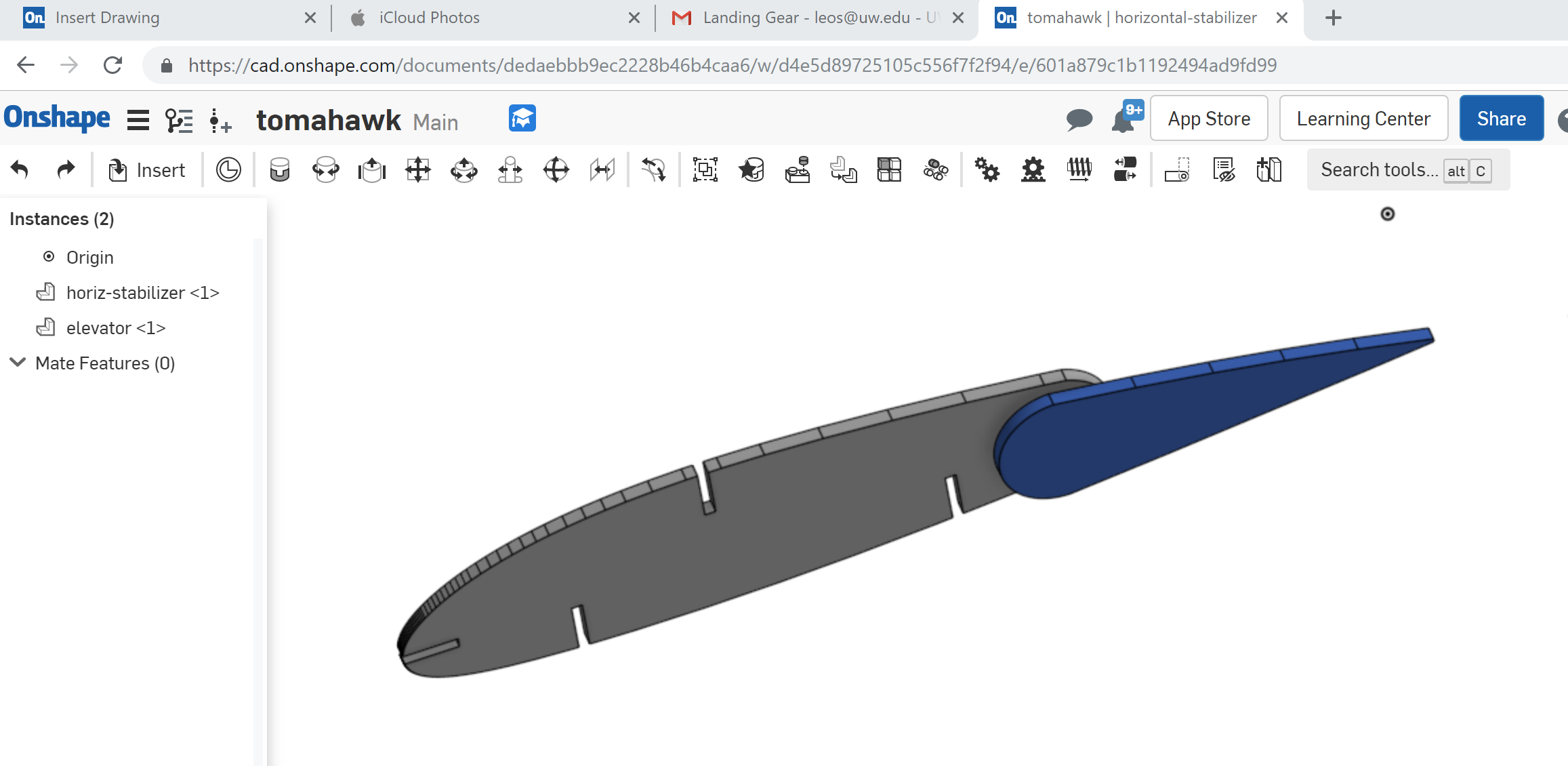
Okay, settle down. Still need the hole. McMaster Carr says to use an 0.131 inch hole size which comes to 3.3274 mm. I'll use 3.33 because it's a pretty number. Back to OnShape, open the sketch, make a circle. Annd ....
WE INTERRUPT THIS ONSHAPE SESSION FOR SOME LASER CUTTING
My name finally came up in the queue. Ironic, since I wasn't quite ready to lasercut elevator hinge parts. No matter, on with the fuselage. Got about what I expected, althought the frontmost slot for the horizontal stabilizer is awfully close to the leading edge of the tail.
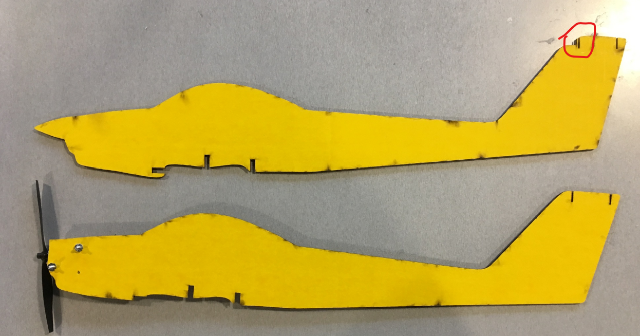
I could get away with the assembly in cardboard, but will need some chamfering for this to work in acrylic. While the plane overall performs much better against the shake test, the fuselage still wobbles left and right.
So what's next for fuselage? The tail is straightforward. All three slots need to be redone from the original airfoil. The whole thing could scoot toward the rear a bit more. Also need more tail material in front of the forward spar slot.
The wing joint is a bit trickier. Really not sure how I'm gonna pull it off in acrylic. A lot of cut and try and chamfers. The cheesing idea is looking beter now.
Imma pivot back to the horizontal stablizer. I might just be able to sneak in a quick cut.
Back to the hinge. Here's the pic I was just about to grab before the laser cutter opened up.
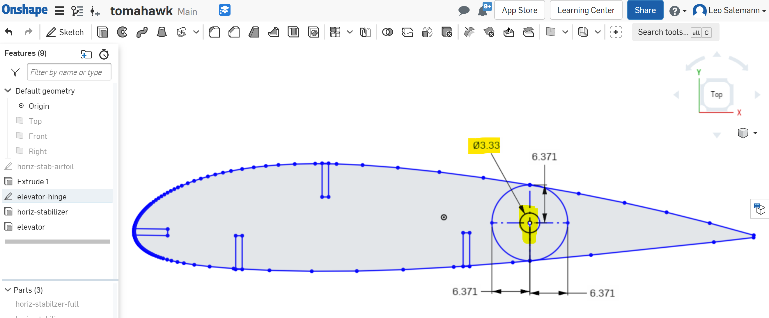
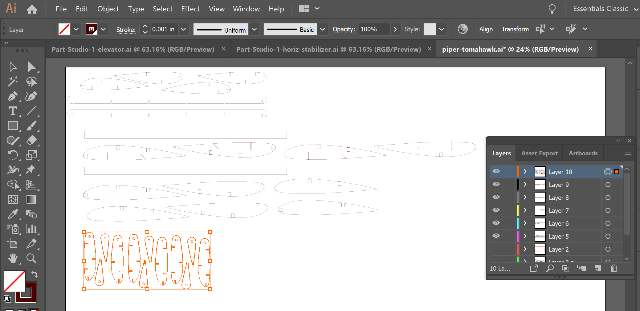
Re-extrude, extract extrustion faces, export to DXF. Pull that into Illustrator for a quick cardboard test. Looks like I can right-click the OnShape Part, select Export to DXF, then pull into Illustrator. In this case, Scale 1: unit = 1 Millimeters works. Arrange multiple copies in Illusrator, using the artboard from all my previous USPS cuts. Rotate them 90 degrees so the direction of the corrugations works out better. Isolate them to their own layer.
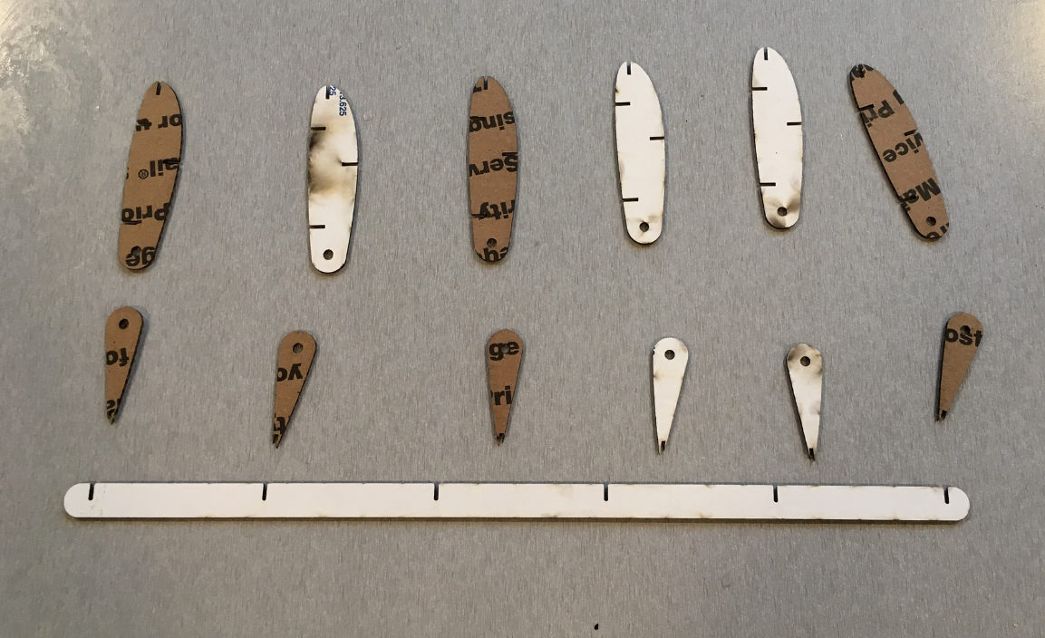
Assembly Notes. Lasercutting was routine and sucessful, although a couple slots seemed to get "double-traced" by the laser. No biggie. The Elevator looks like a symmetrical teardrop but I don't think it really is. Kinda hafta guess which elevators are upside down vs. rightside up.
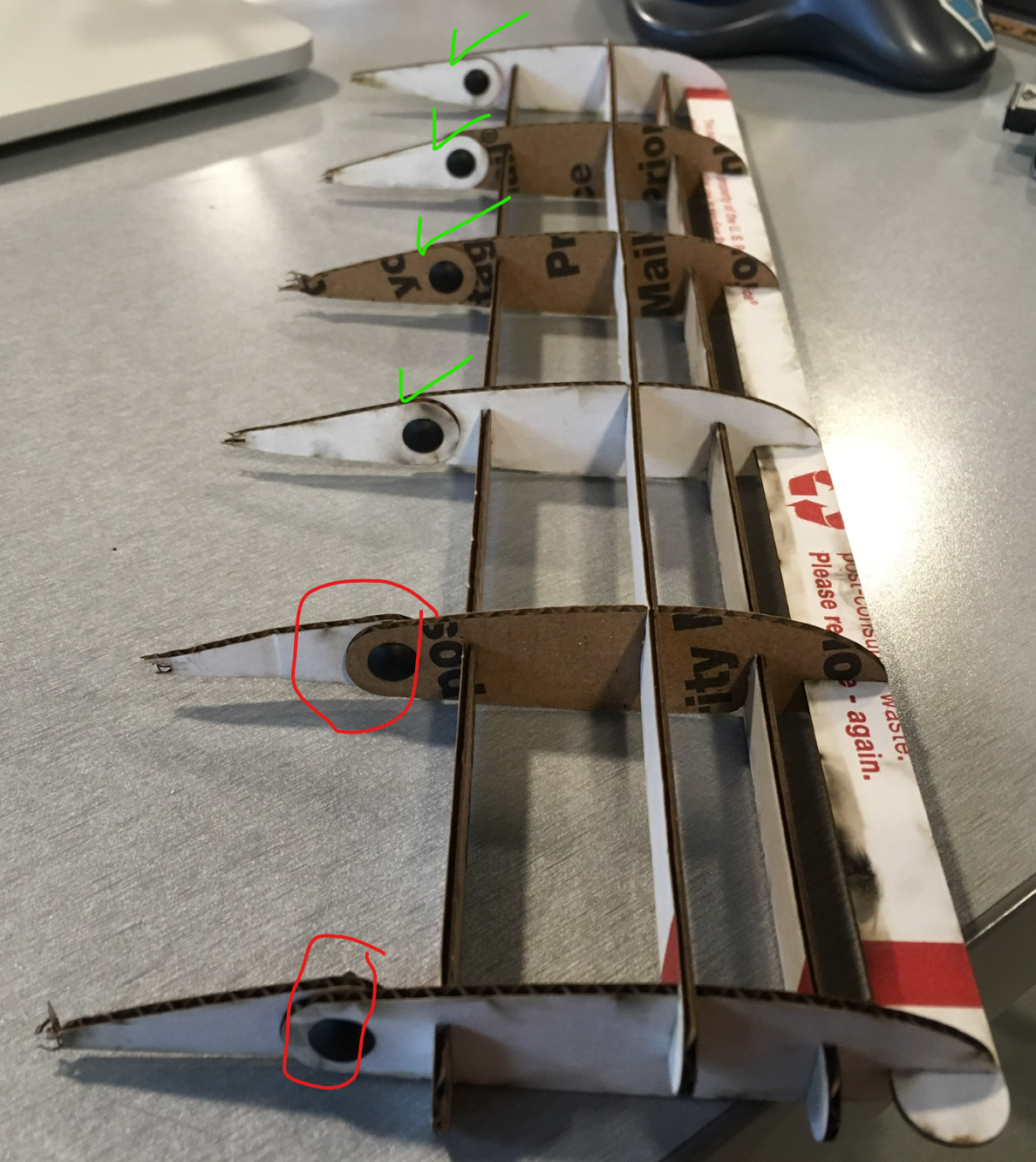
Turns out it's important to pick a side and stick to it. See first pic (bad) vs. next pic (good).
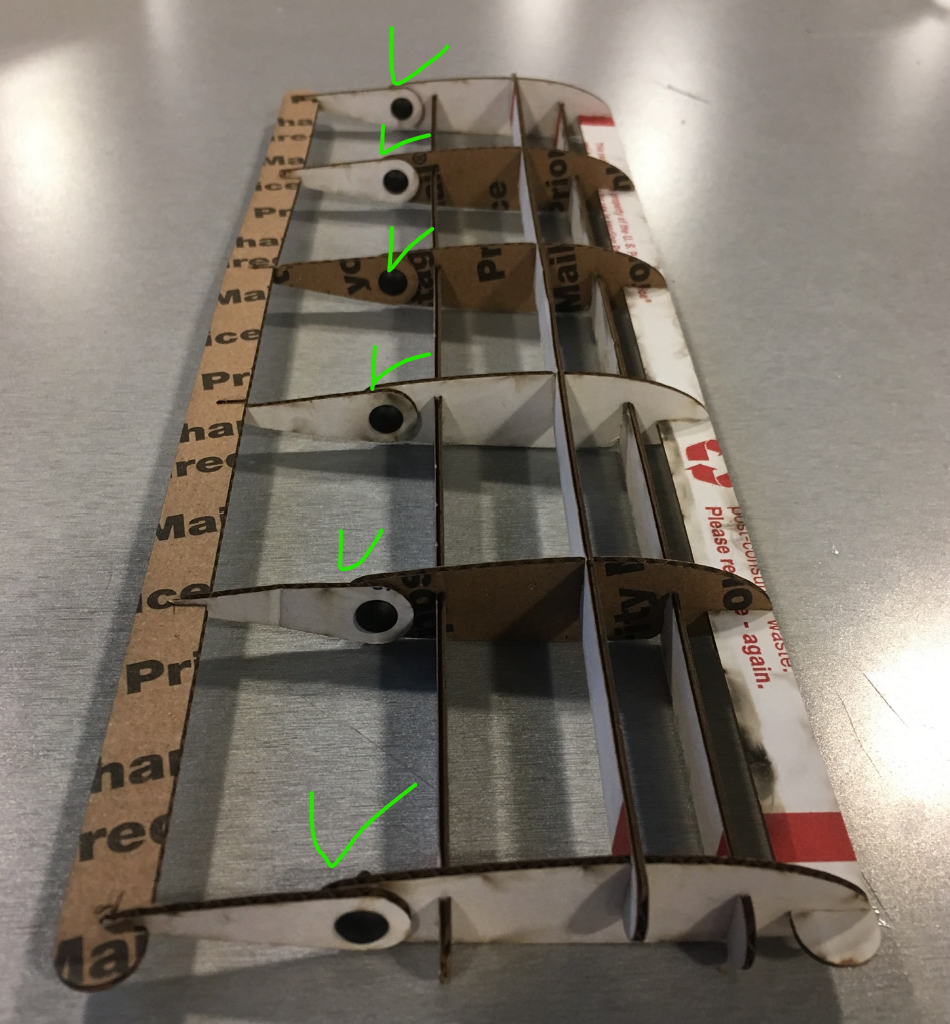
Now about that Trailing Edge It sucks. Need to chop off more of the elevator. After diner.
So the elevator hinge plan basically worked. Need to fix up the way the spar mates to the trailing edge, then try a couple CNC cuts. Pull the elevator spar into OnShape and check things out. Trimmming the elevator was easy -- just move the rectangle and add a cross line.
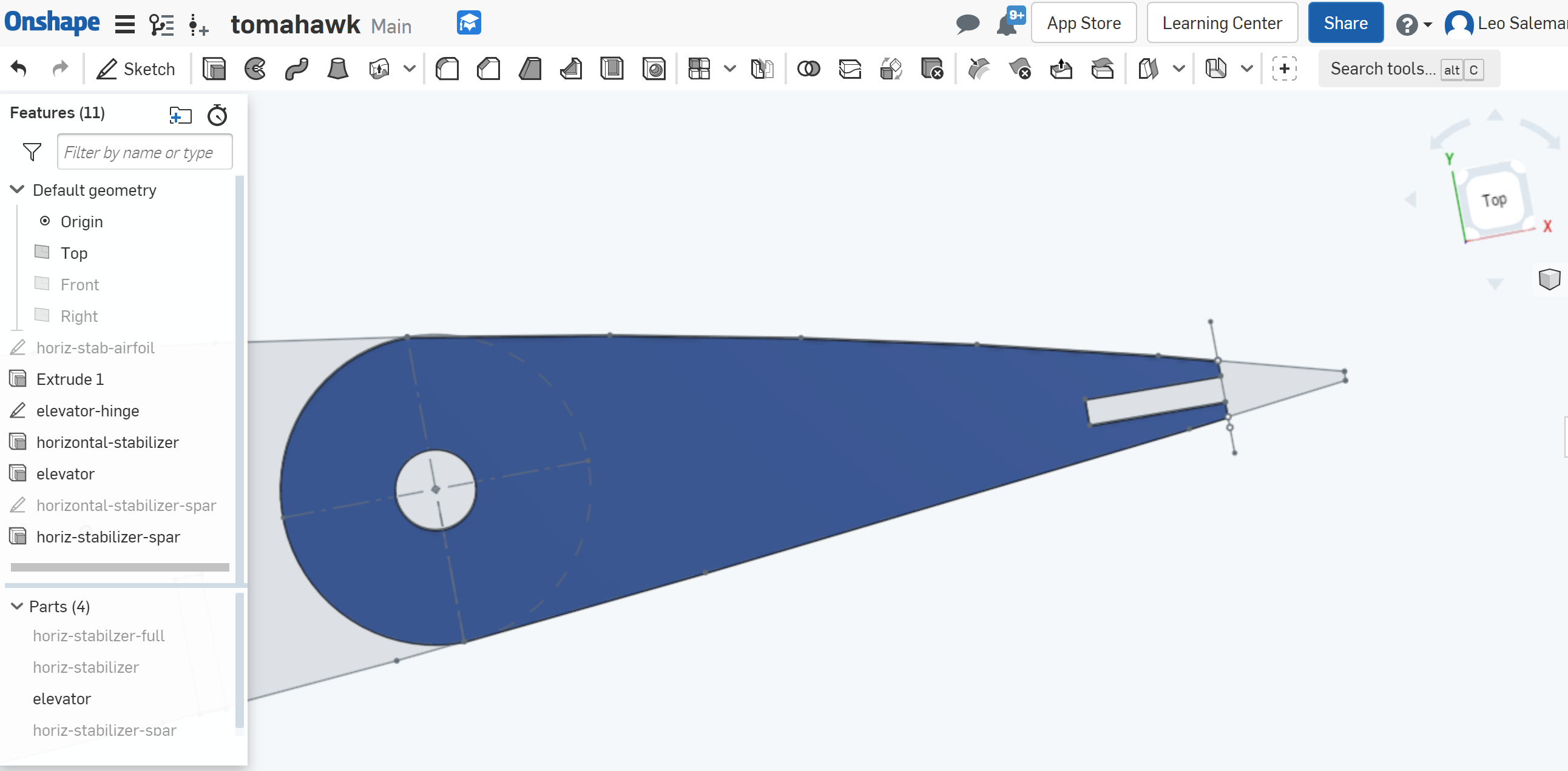
Couldn't get the mating surfaces to work. Just need to hand-transform the parts to get them to move and just kinda be next to each other. The Revolute mating between the main stabilizer and elevator worked, though. Go through the same old OnShape->DXF->Adobe Illstrator chain, Using Scale 1: unit = 1 Millimeters when Illustrator asks about units. Looks better on the lasercutter bed ...
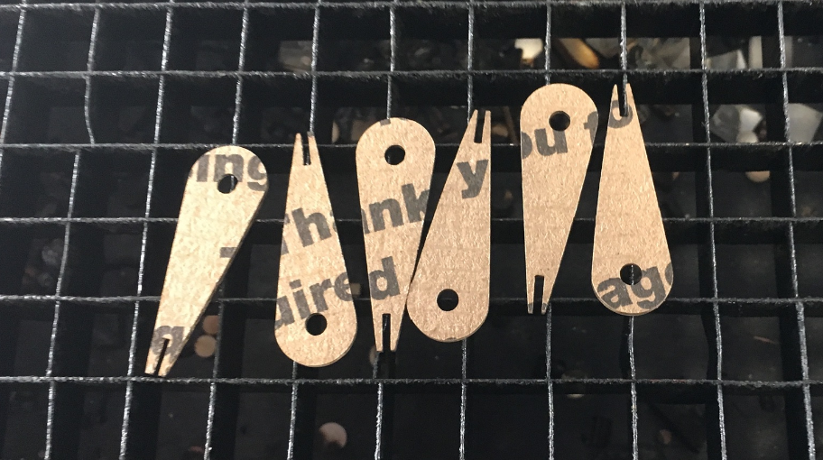
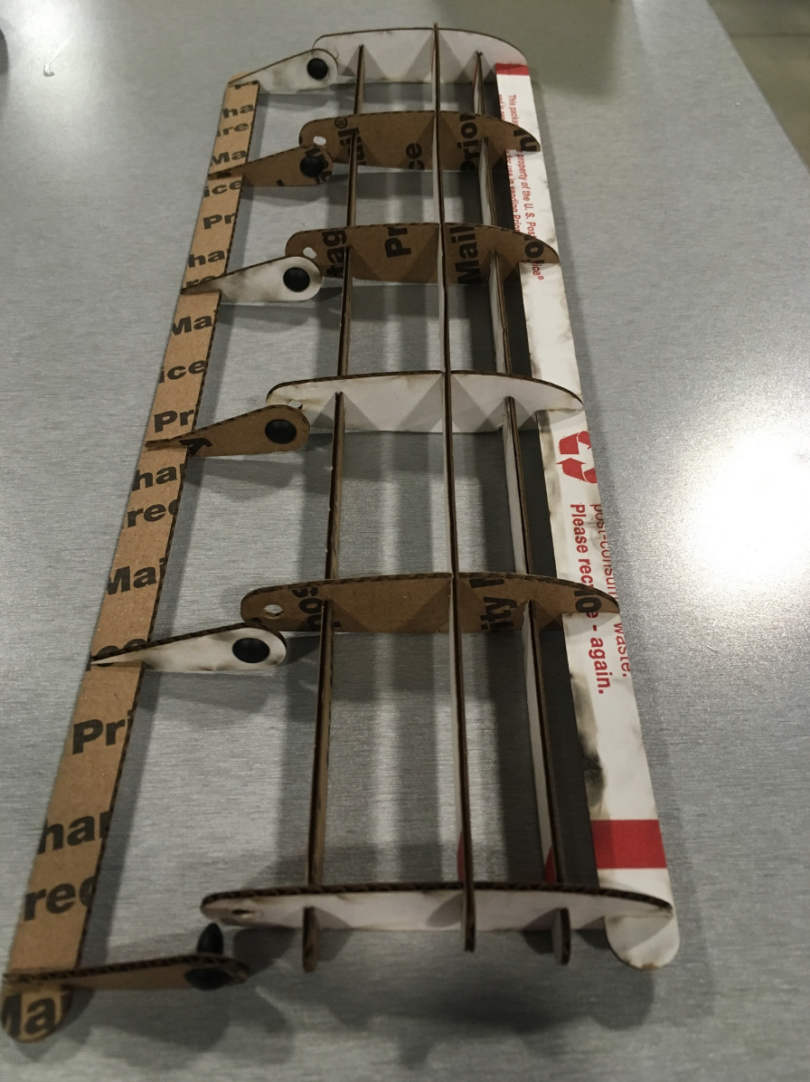
Looks better assmbled too. Definetly better to attach the elevator foils to the trailing edge spar first...
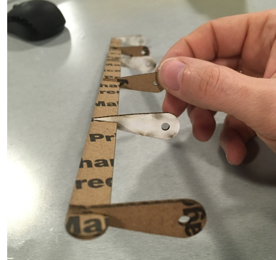
...then pin it to the horizontal stabilizer.
We've got solid DXF that proved itself on the laser cutter; let's try CNC. Check assignment 5 for a refresher on the tool chain. Look like I just take the DXF I exported from OnShape for Illustator, and load it in KiCAD.
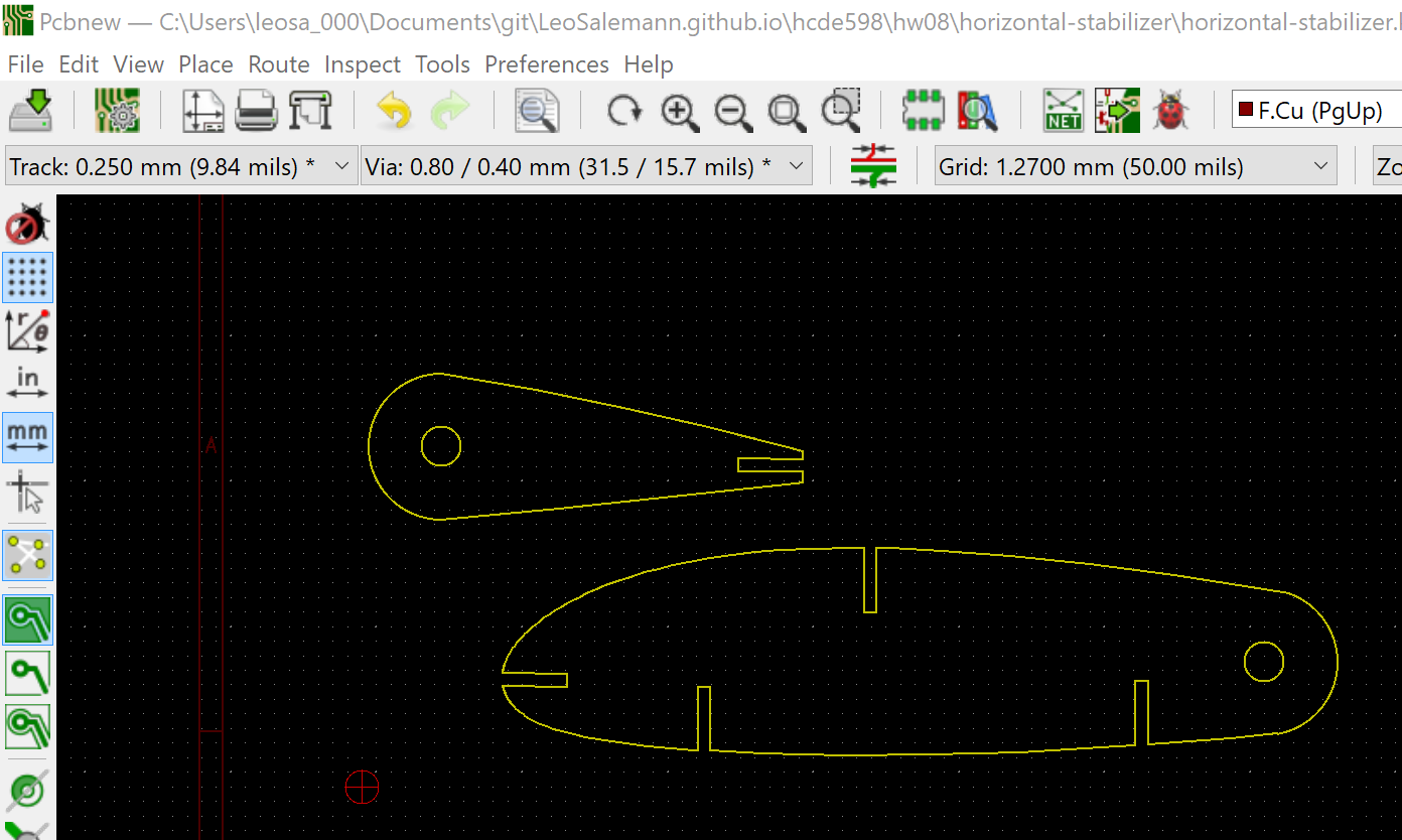
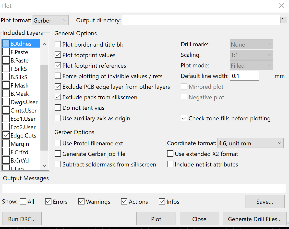
Now a File->Plot in Gerber, de-selecting everything but edge cuts.
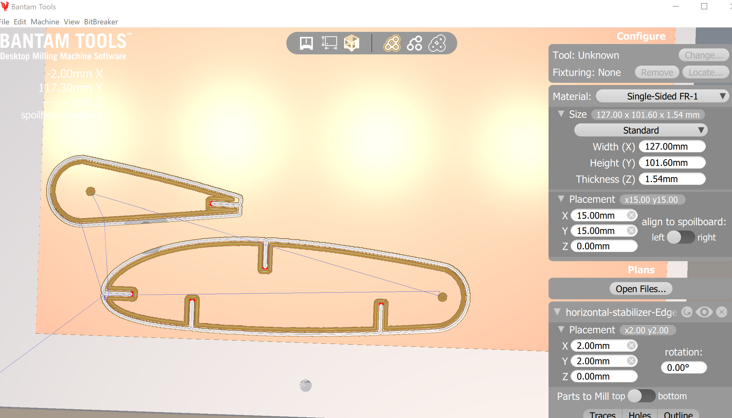
Lie #1: We'll tell Bantam the material is 1.48mm thick instead of 1.43mm.
Lie #2: We'll also say it's hovering 1.65mm instead of 1.67mm. Together, these lies will hopefuly ensure Bantam cuts all the way through while still not touching the actual aluminum spoil board.
Translating everthing into Bantamese:
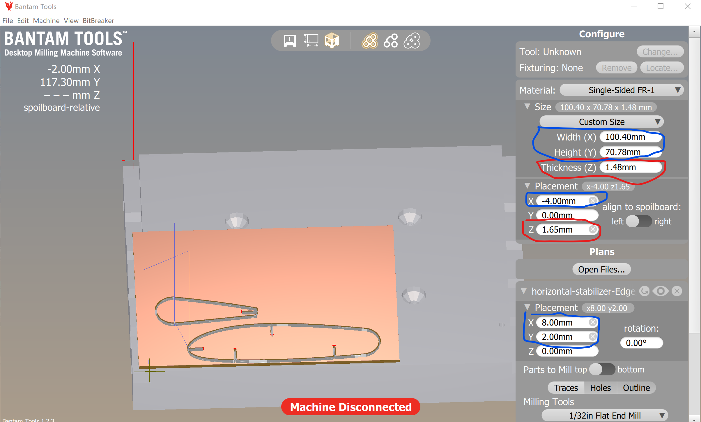
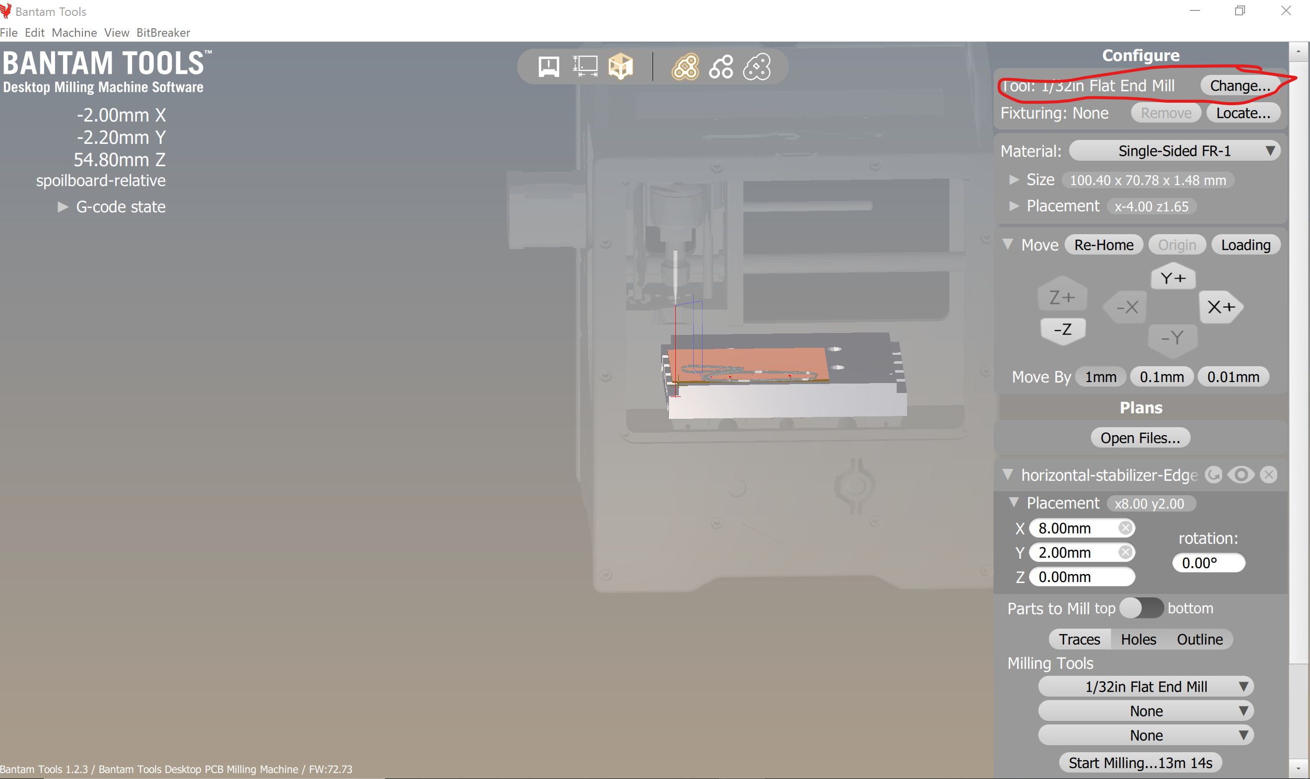
On to the Bantam Mahcine First thing, make sure the real physical tool (1/32" end mill) is installed. Then, run Change... at the very top-right of the UI to induce the tool locating process.
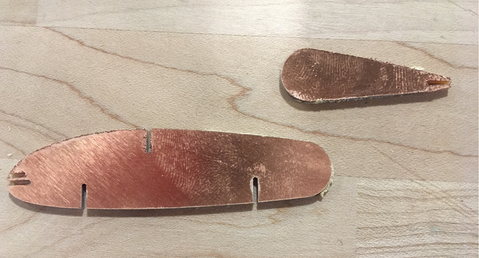
Crap. It missed the holes. Also got a second slot in the leading edge for some reason. On the plus side, at least they cut all the way through. Test-fitting failed though. Slots are too narrow for the USPS cardboard.
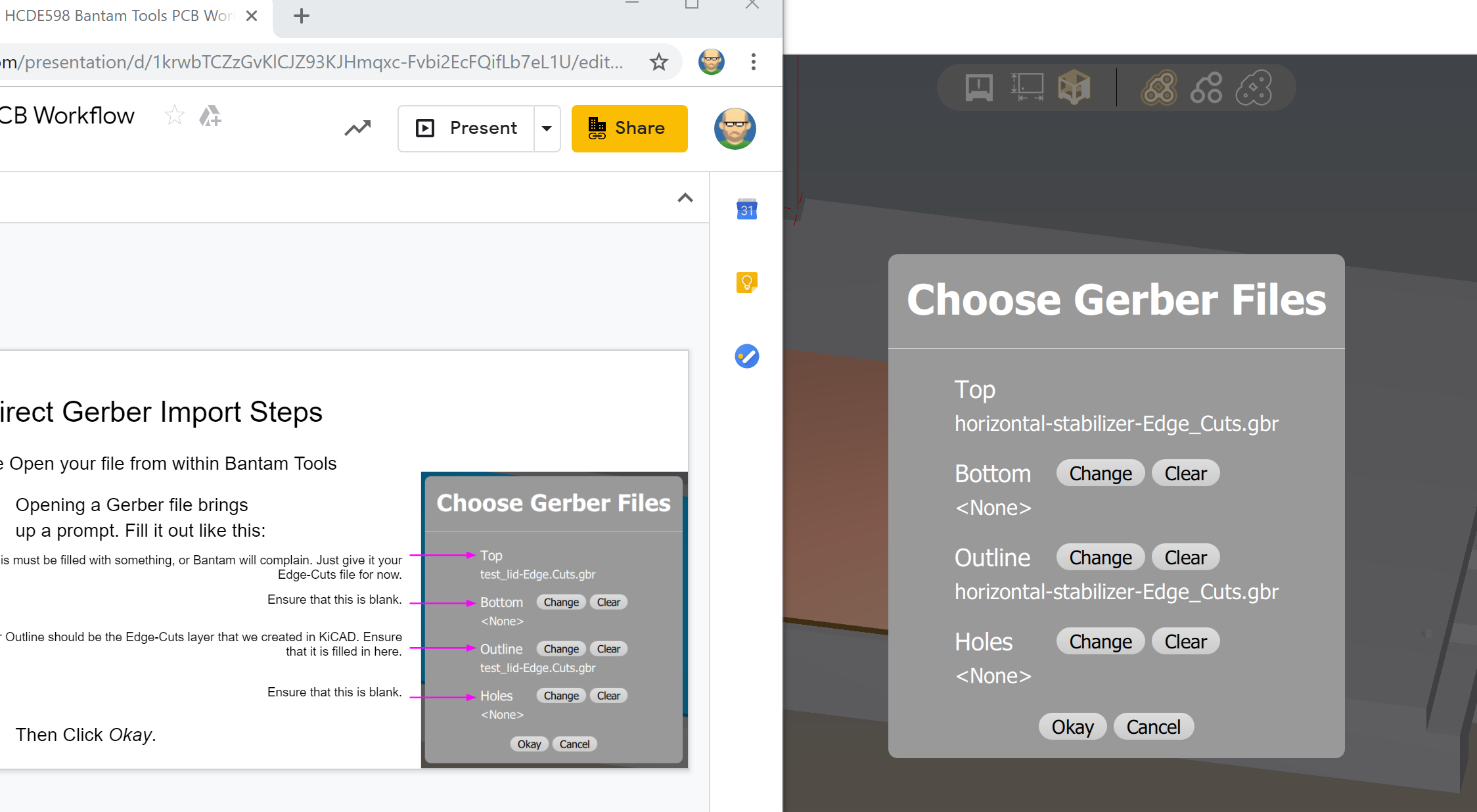
Allright, so what went wrong where? A quick scroll-up on my web page shows the holes made it into KiCAD. They don't show up when I toggle the Bantam Holes option in the UI. Closing time; I'll have to look at it tomorrow.
Okay, so my two major problems from last night are:
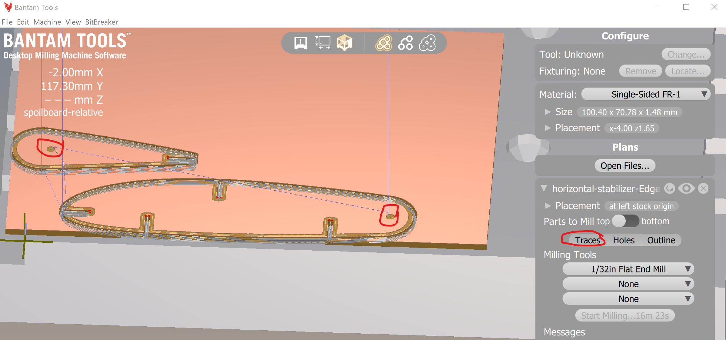
Aha! The holes are so small that they show up as traces but not holes!
Okay, I have a pretty strong hunch that the OnShape edge-offsetting that I have to do for the slots will take care of hole sizes. It's caliper time.
So in OnShape, Imma extend outer edges inward> by 0.528mm to get wider gaps, and extend the rivet holes outward by the same amount.
And once again I managed to document a crapload of steps and comentary in Assignment 5, yet negelected to record the actual extension step. Back to menu-hunting again. Ok, for the record, the function in quesiton is offset surface. In practice I used half of 0.528mm since both sides of the notch will be offset. Turns out negative offsets are not tolerated, but you can use the Opposite offset direction arrow to accomplish the same thing.
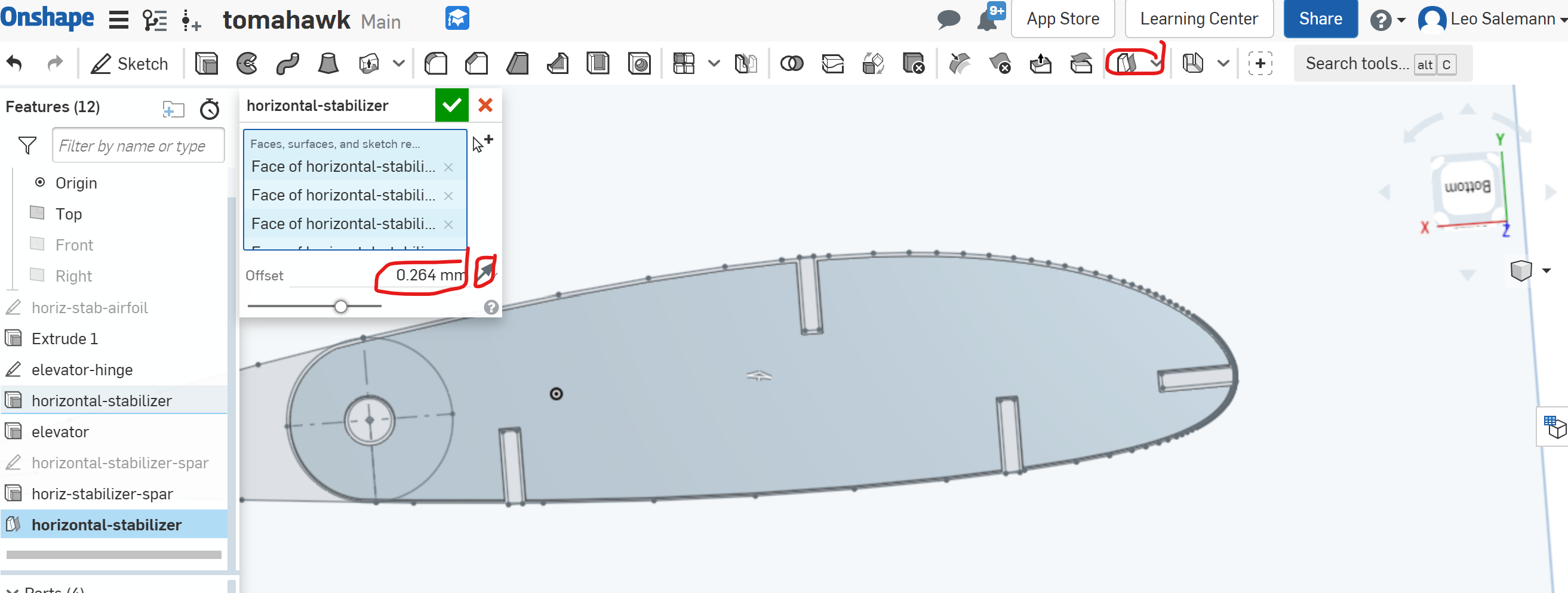
Now that I've grocked that part, Imma add arcs to the bottom of each slot to appease Banatm even more. Pretty easy, just conver the line at the "bottom" of the slot to a construction line, then add a midpoint, then add a 3-point arc. With a bit of finnesse, it "snaps" to an arc whose radius matches the distance from the midpoint to the slot edge. With that done, re-do the Offset Surface and I'm ready for my next Bantam session.
Brief moment of frsutration when Offset Surface claimed it couldn't do anything after I added the arcs, but it resolved itself once I droped the delta form the 5mm defual to the 0.264mm I actually want.
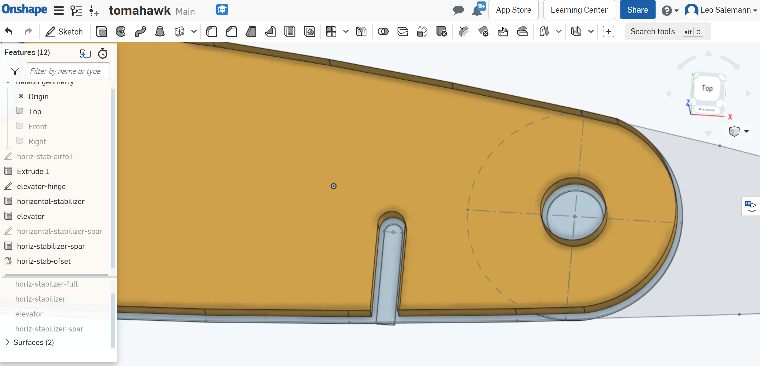
Better, but still no holes.
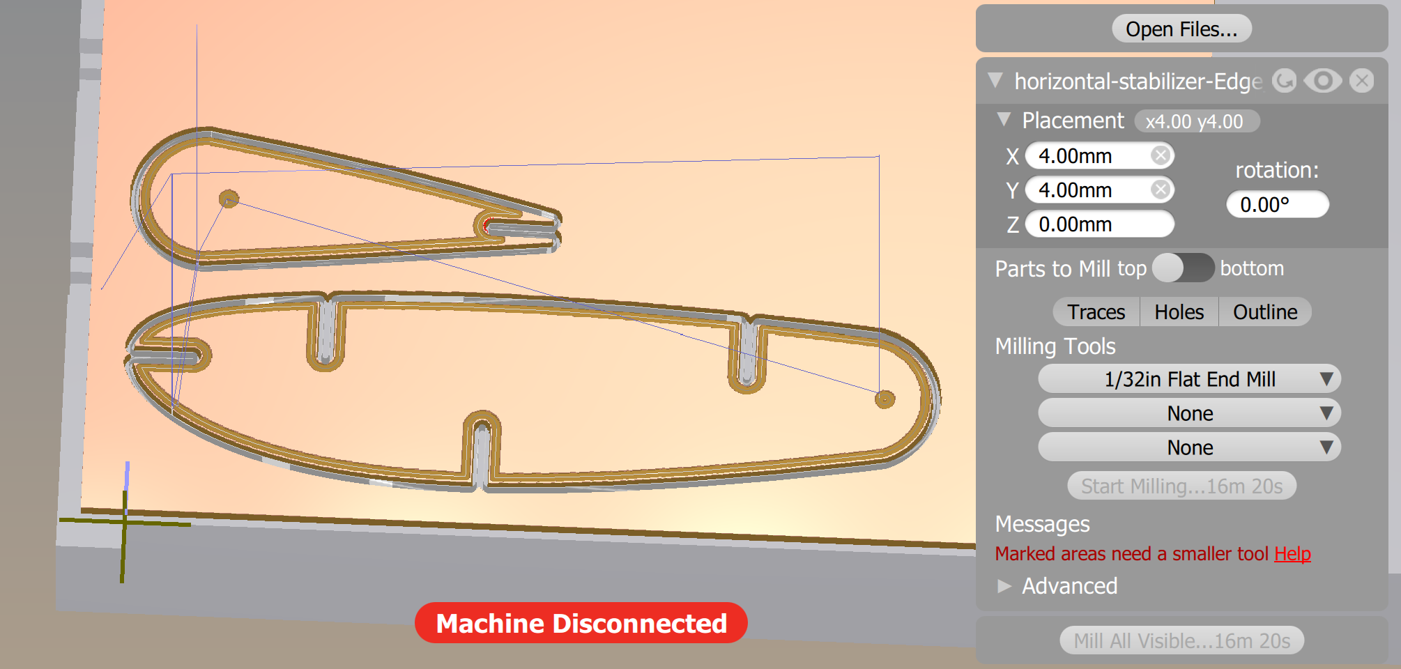
Tried the SVG option. no luck. Having a hard time believing the holes are too small -- they're bigger than the slots. To heck with it, diner time.
I have a couple ideas. Gonna make one hole "stupid-big" and remove the other one with a pair of arcs. Here's the wierd thing. When I'm in Bantam and I switch from 1/32 to 1/64 end mill, the "engraved hole" diameter shrinks. I expected it to turn into a ring. I'm thinking the hole is being treated as a "dot" and not a "donught"
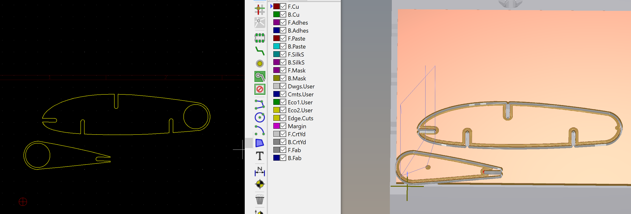
Stupid-big hole test failed; let's try arcs. Dangit, no improvement.
Try Fusison 360 Found a Bantam Artticle on using Fusion 360. Seems like the examples are little out of date. I got a hole, though not sure if It will go all the way thru. Exporting as STEP form KiCAD, had to export as STEP form OnShape for the elevtor. Under Manufacture use 2D /contour.

It's 9pm, and I got Nothing. Endless tweaking with Fusion360 and the regular KiCAD->Bantam tool chain hasn't helped my hole problems. I should pivot to the fuselage. Maybe get some help from Joshua tomorrow for CNC. Scroll back up in my notes, review my fuselage options. Given what I've learned with OnShape, I think I can bring in the fuselage and airfoils, and try some "cheesing." Imma start in Rhino though, and make a copy of the fuselage with "smoothed out" airfoil integrations.
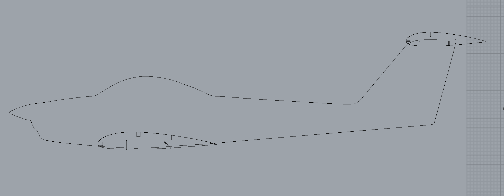
All right. Export as dxf, create sketches in OnShape then import from dxf direct to sketch.... and nothing! After burning another 30 minutes of my life, I remembered to Put Rhino into metric units, export dxf/CAM Metric, Import into frickn' OnShape specifying frickn' millimeters.
Also, forgot to scale1D all the slots that lay on the fuselage.
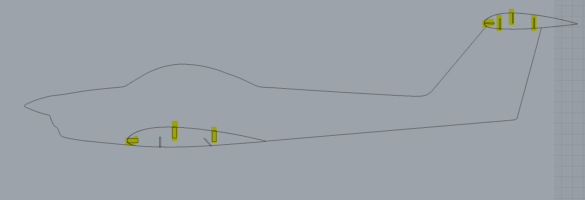
Now we can pull into OnShape by exporting dxf/CAM Metric, Import into frickn' OnShape specifying frickn' millimeters. Now all we goatta do is cheese it ...
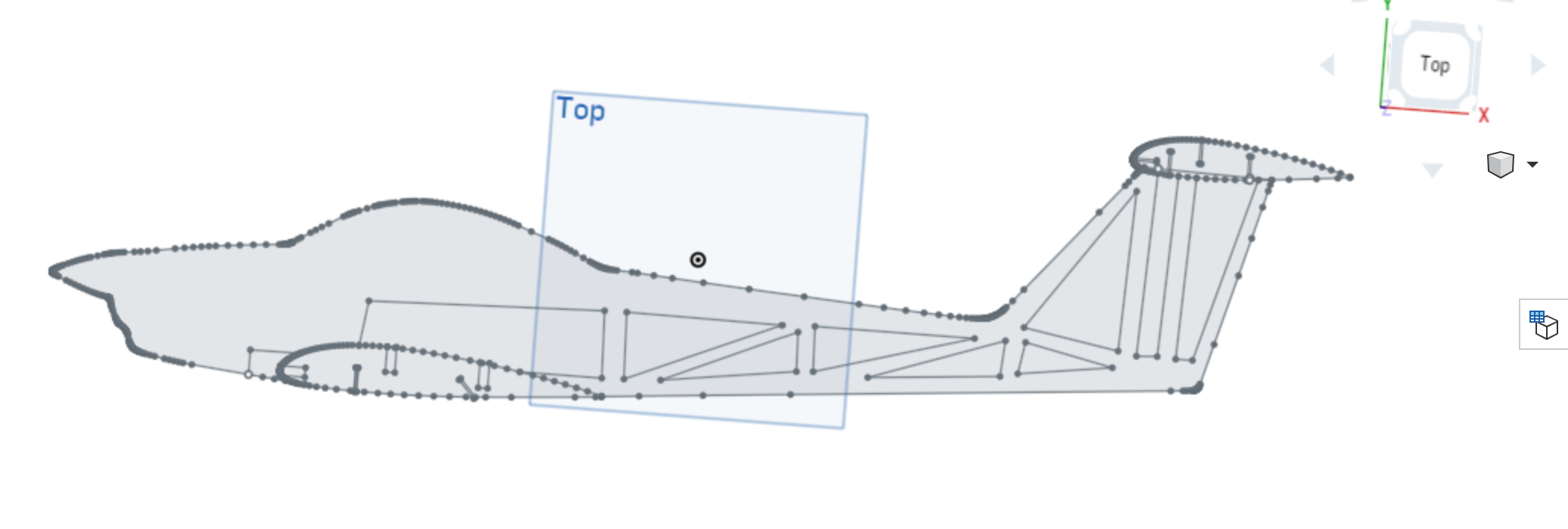
Extrude it ...

Laser cut it ...

Assemble it and ... crap. I need to lop the trailing edge "spike" off of the tail. On the plus side, it assembles well and feels really solid.
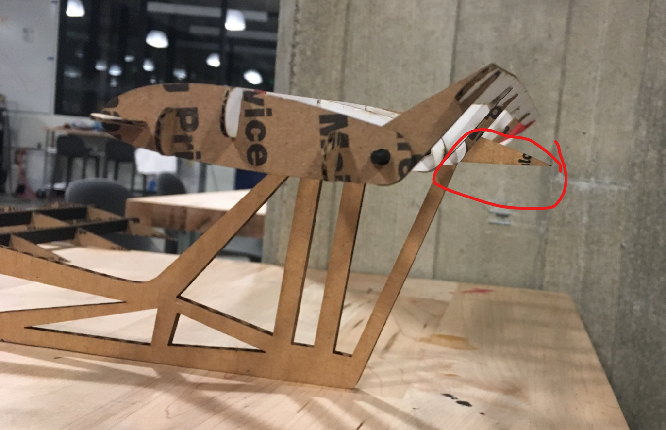
Moving foward, I think I overdid it on the cheeseing, particularly near the wing. Fuselage is realy flimsy. The wing doesn't feel like it's going to fall out anymore, this design would be too weak even in acrylic.
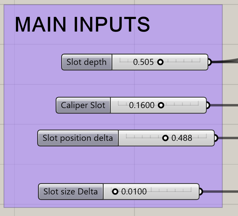
I'm actually close in the laser cutter queue. Bang out a guage for acrylic. Pull the two grashpopper files (hw02-guage.gh and hw03-guage-3dprint.gh) and check units. They're both inches, so stick with hw02-guage. Before I do anything, grab a pic of the settings in their current state:
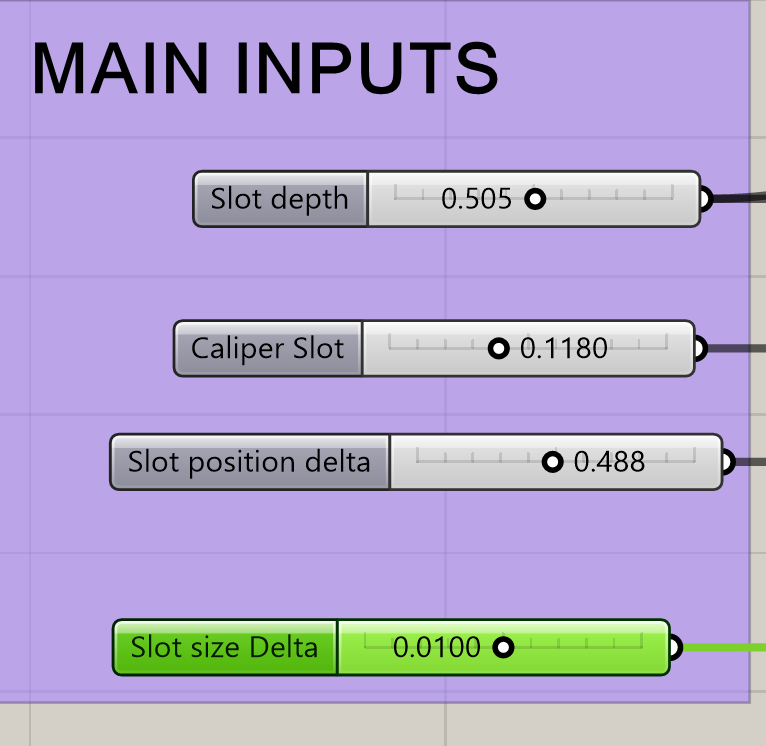
Now I can tak a caliper measurement of the acrylilic: 0.1180 inches. Dial in the max range for the delta. Make it noticable but not too extreme. Going with 0.015 as the max; 0.01 as the initial value.
Open the Adobe Illstrator file from Assignment 4 (Fowler Flap) since it has the patterns of what I cut out earlier. Save as hw08/acrylic-dark.aio (name AI files after material) Do some clever rotaiting to get the gauge to fit among the other layer.
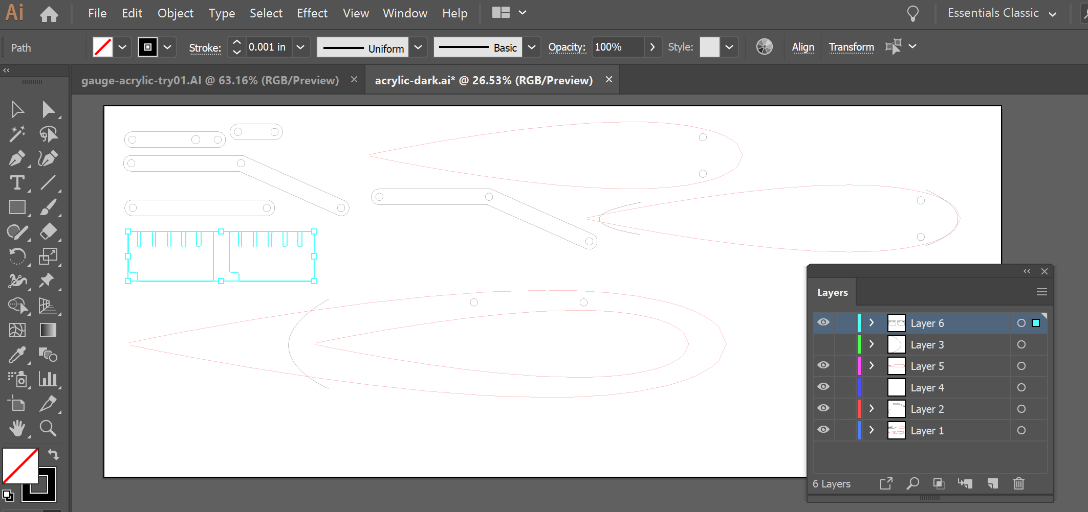
Aaand ... the queue's going to be 2+ hours. Back to documentation and planing mode. At least I've got one item in the hopper for when my number comes up.
Learned a KiCAD hack from Joshua that I would never have thought of by myself. Added a footprint(looks like a microchip), then add a drill hole. Query my CAD circle to get it center; use that to set the X and Y of the hole. Also set hole size. Plot, pull into Bantam. Bantam knows the hole file ie there.
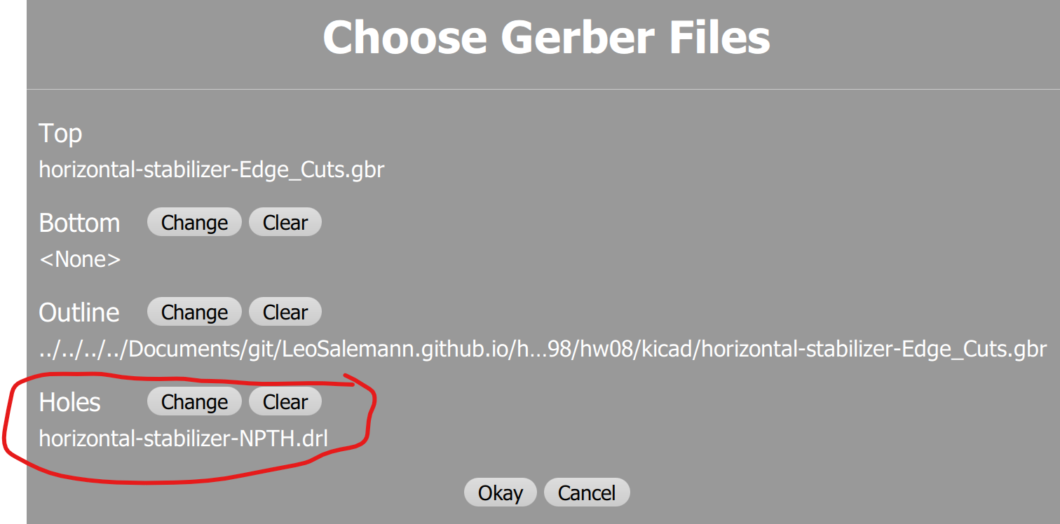
Holes! I got Holes!
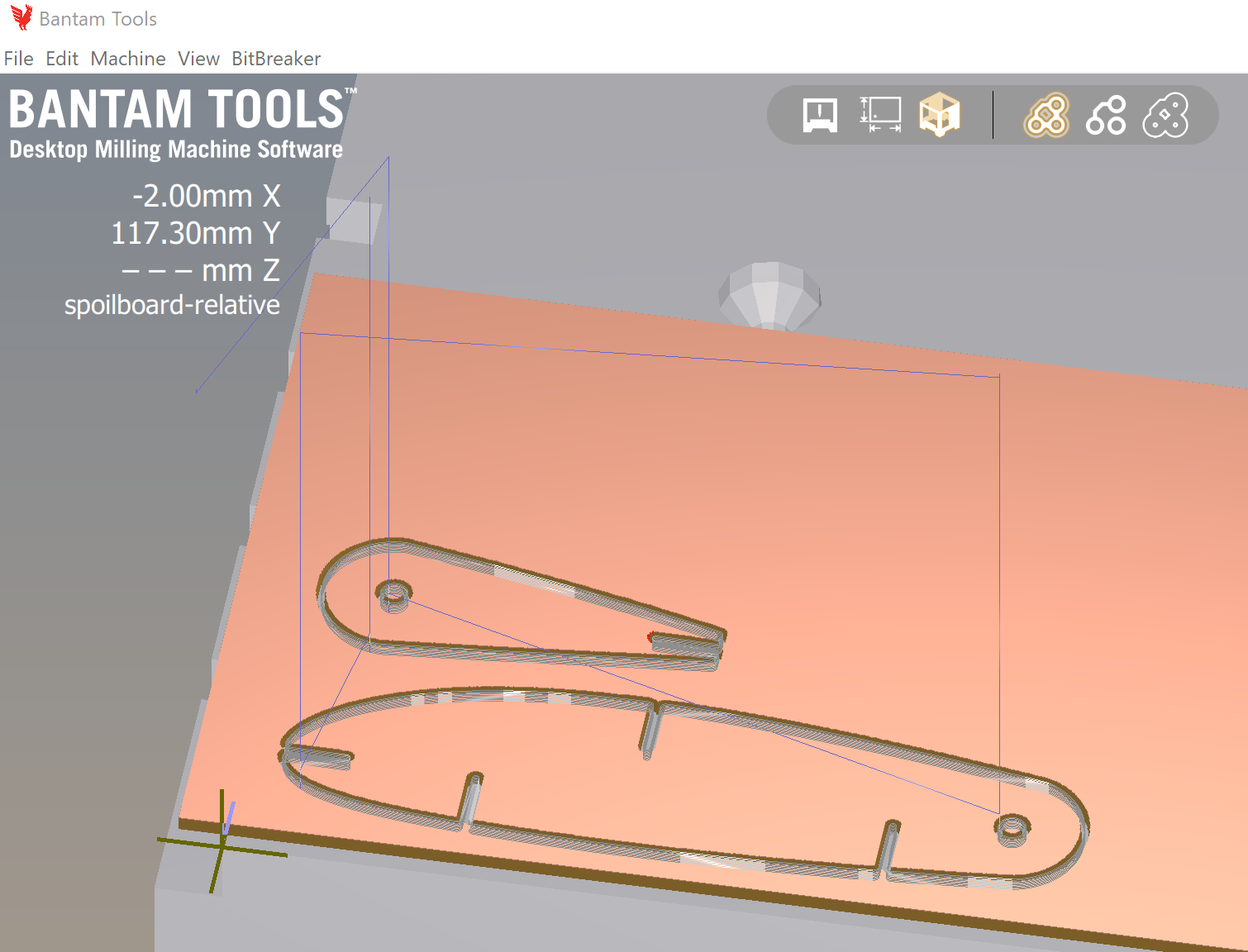
Tempting as it is to run this, I'm too hungry to deal with high-velocity tooling right now. Dinner break
Milling underway. It's starting with the holes. About 15 minutes for one elevator hinge. Half an hour for a pair. Fourty five minutes for another three. So I should mantain one bantam fiole with a single elevator/stablizer combo; and another bantam file with a pair.
It's done.
Parts look good.
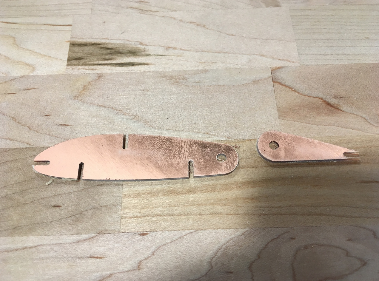
Next FR1 It's 1.67mm thick, same as last time. Load it up and go. Gonna re-do the Tool-chaging procedure because I'm paranoid.
Oh, Crap! My material came loose. The whole FR1 sandwitch is sliding on the aluminum spoil plate. Not enough tape; too much dust. Power off istead of emergency stop. Re-home to get the tool out of th way. Rapid to loading to swap the material. Got plenty of FR1 so Imma just tape up another pair and get going. Re-do the Tool-changing procedure yet gain. Aaaand we're back to the races.
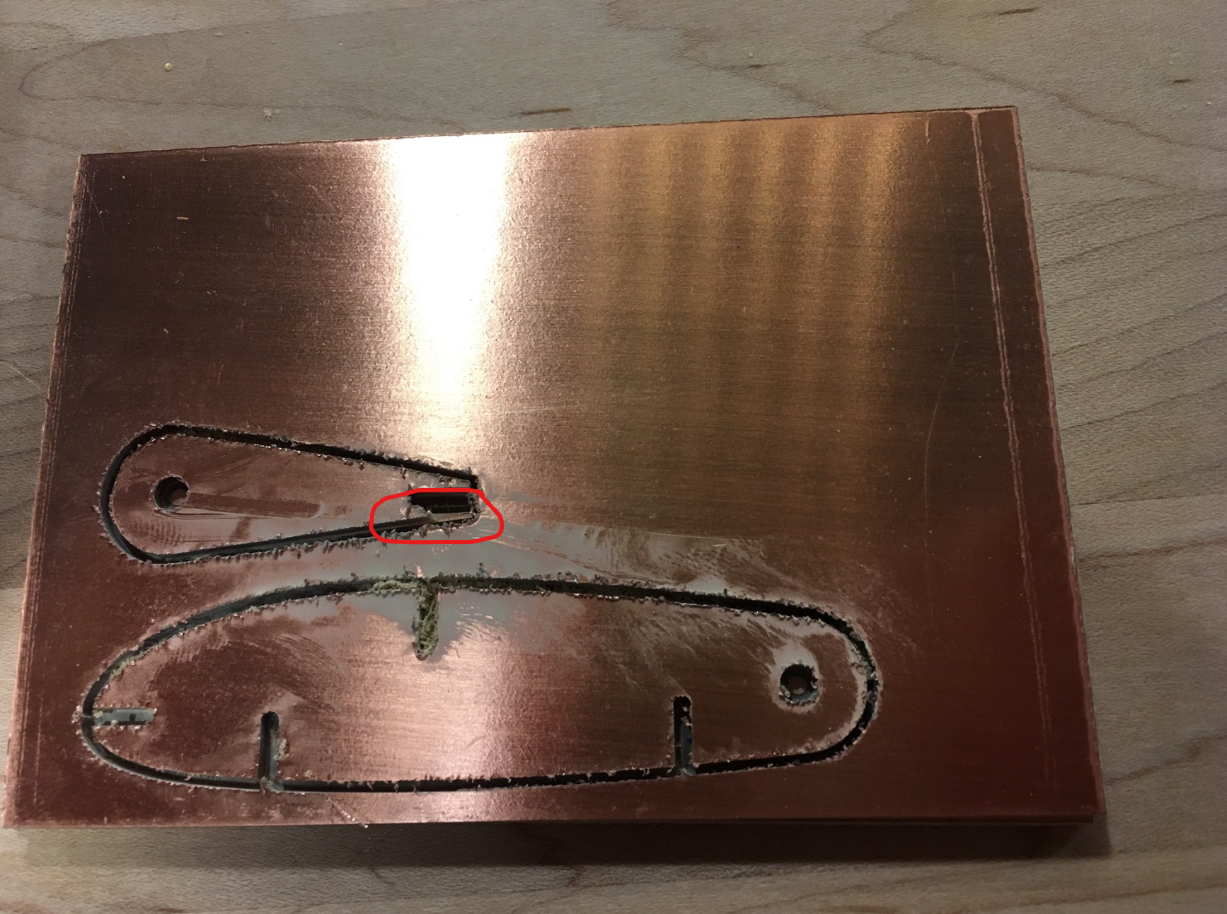
Minor Defect
A little piece of the trailing edge came off, but I'm not gonna let
that stop me.
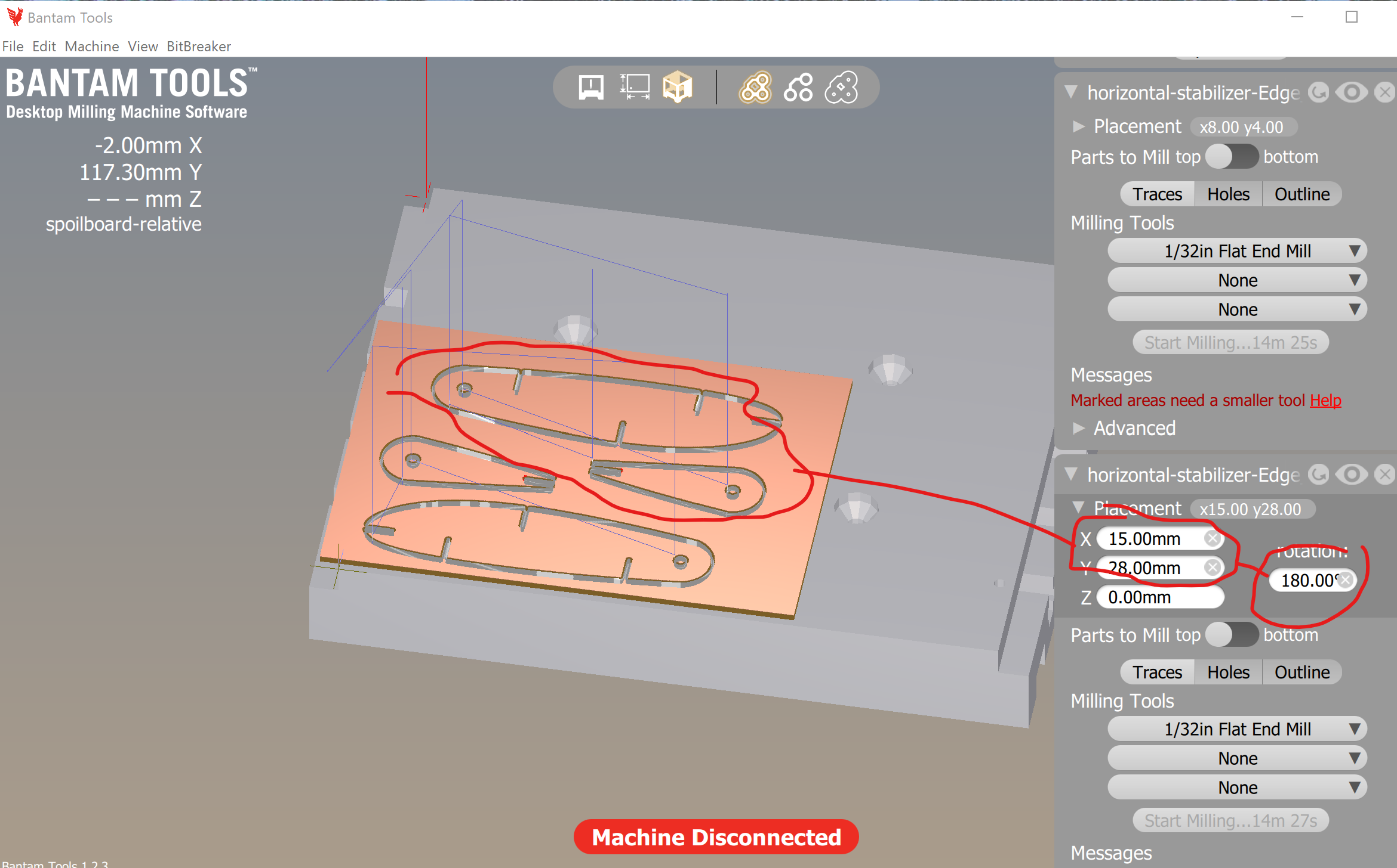
Go for two.
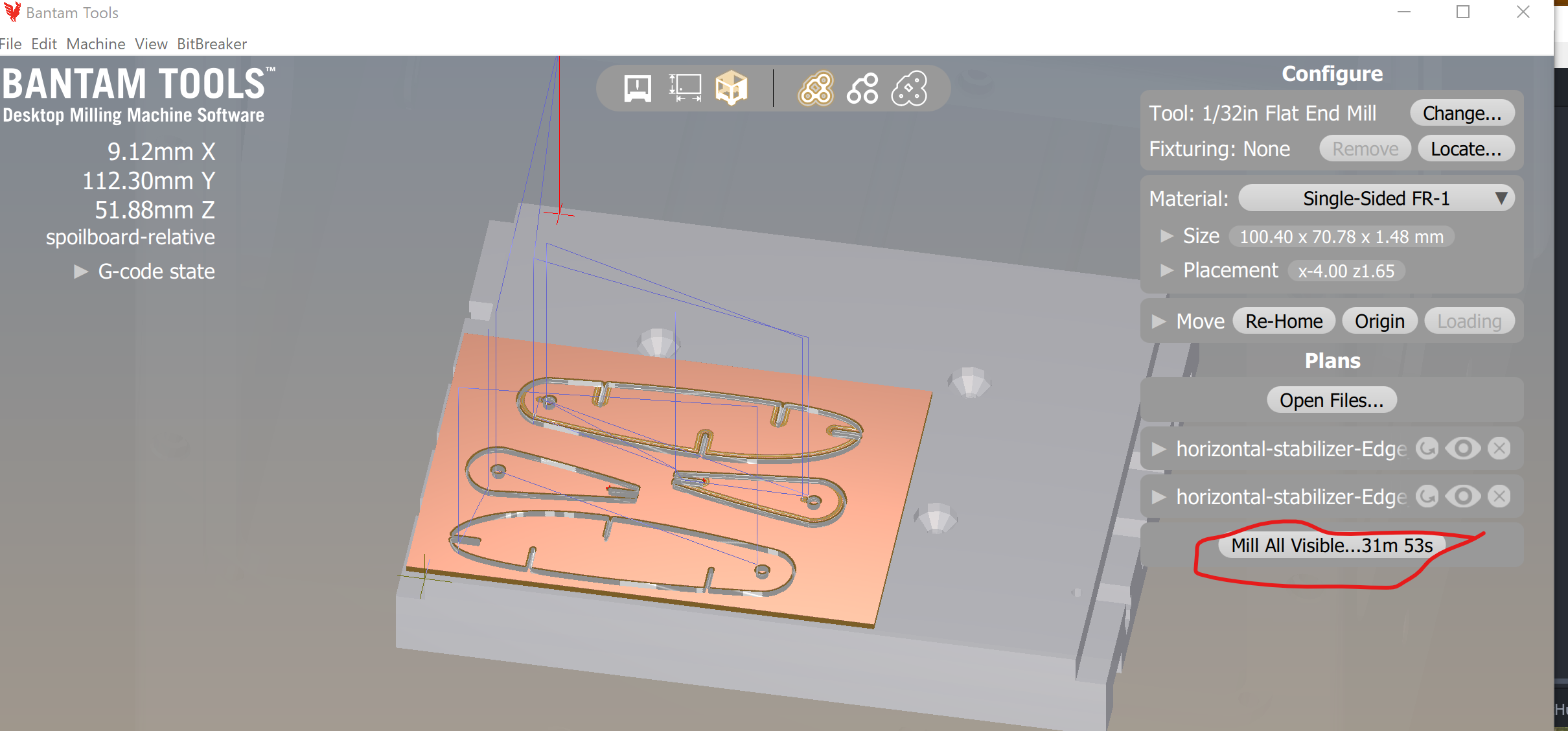
Load the same gerber/hole file. Move it so it plays well with the
second.
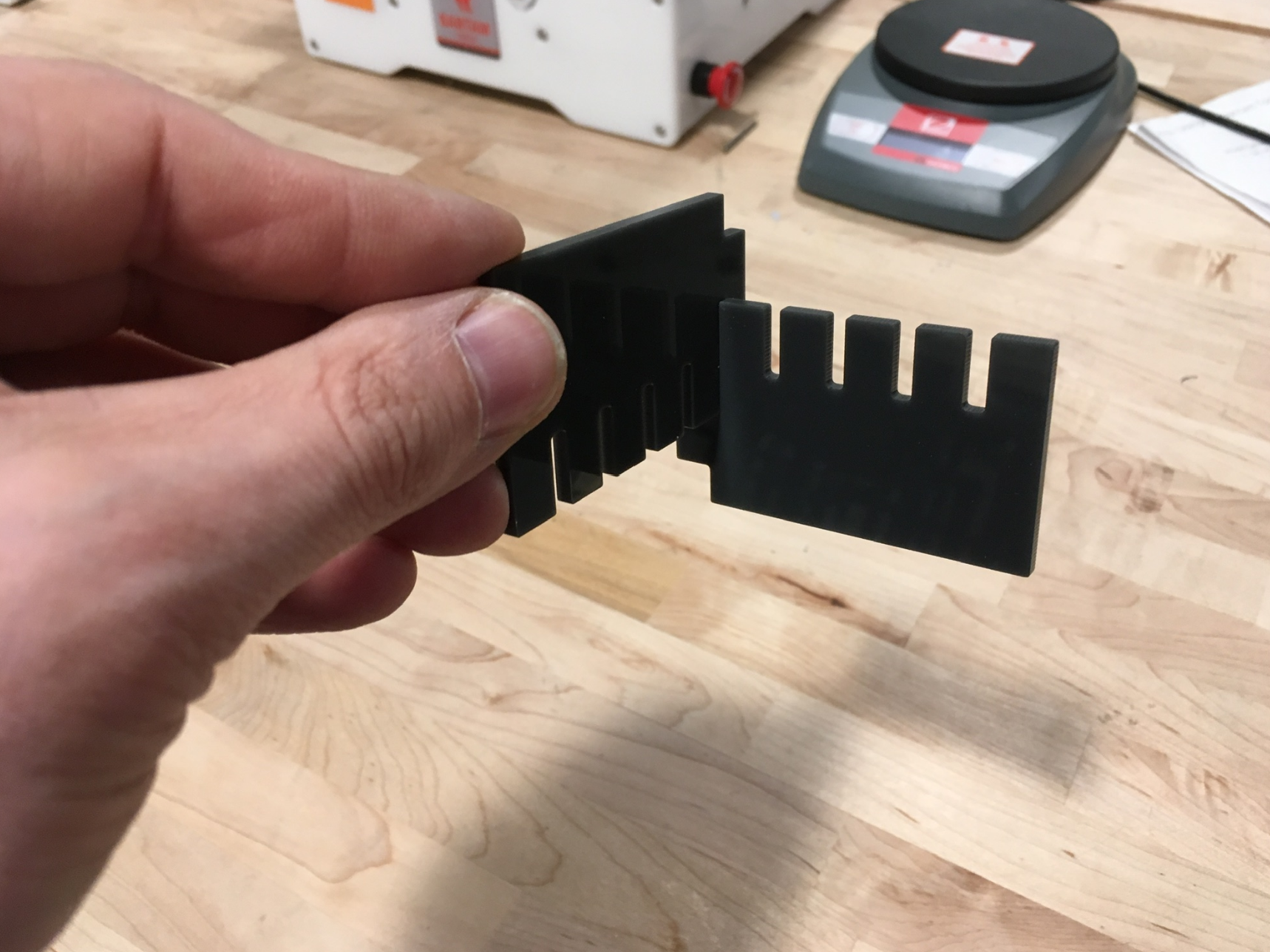
Laser Cutter's Avaialble! Cut my acrylic gauges. Smallest notch fits fine. Good thing I didn't stop at four slots instead of five.
Back on Bantam, it looks like I had traces turned on for one of them. Oh well. So Now I have Three good ones, Two good enough with traces, an one slightly broke. I'll load up one more pair.
Back to the Fuselage
Best use of my time while Bantam's spinning. First-thing, lop off
that extra elevator piece from the tail in Rhino.
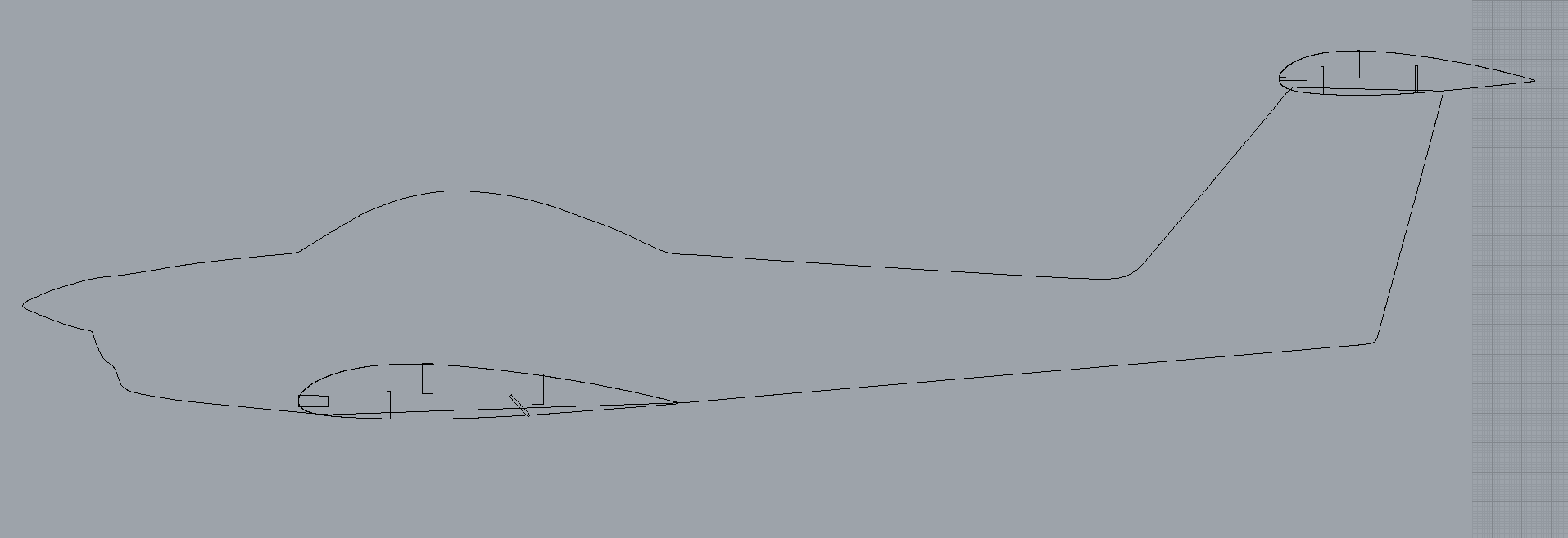
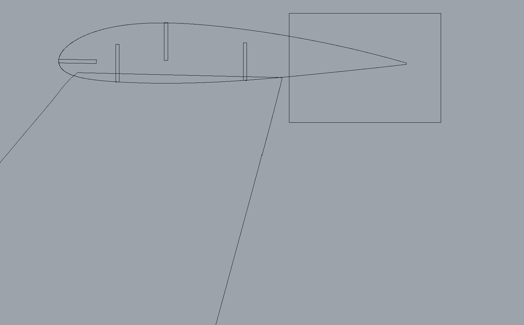
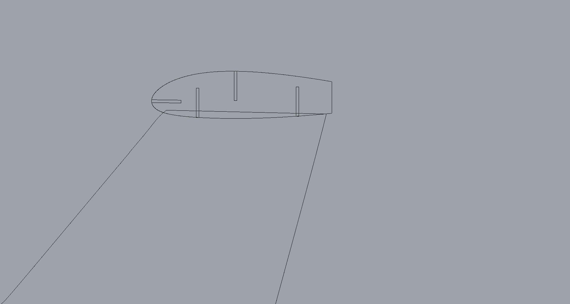

So Here's How it Ended I printed 2 copies of the fuselage in clear acrylic, two more in dark. No time to assemble at the MILL; I'll be doing that at home. Hoping by "stacking" the fuselages I'll have something rigid enough to keep the wing from flopping.
Here we go. First thing is to disassemble what I have. I've got new fuselages and airfoils, but will be re-using all the spars. First thing on my mind is wing wobbliness. Need to see how many fuselages it takes to smooth things out. Starting with one of the main wing spars, it doesn't seem like any stacking is going to do it, so Imma just use the two clear ones and live with the consequences.
A clear canopy without paint
My initial intent was to peel all the protective paper off the clear
acrylic, then paint every thing below the canopy. In stead, I'll
use an exacto to cut and peel just the canopy part, ad leave the rest.
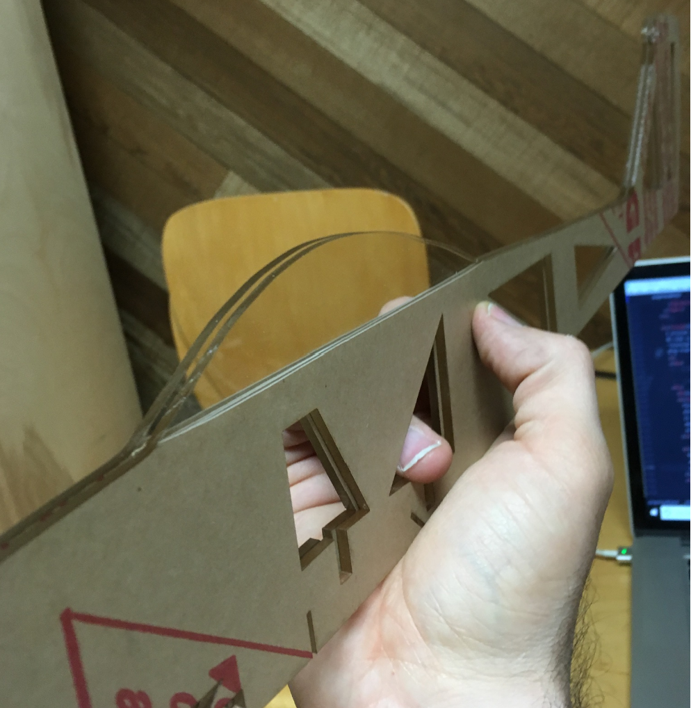
Let's make that wing.
Disassemble the rest of the wing. Use old spars and the new airfoils
I cut at the last minute. Slide the leading edge spar into the notch
at the two fuselages, then add all the airfoils. This is where I regret
not having time to chamfer.
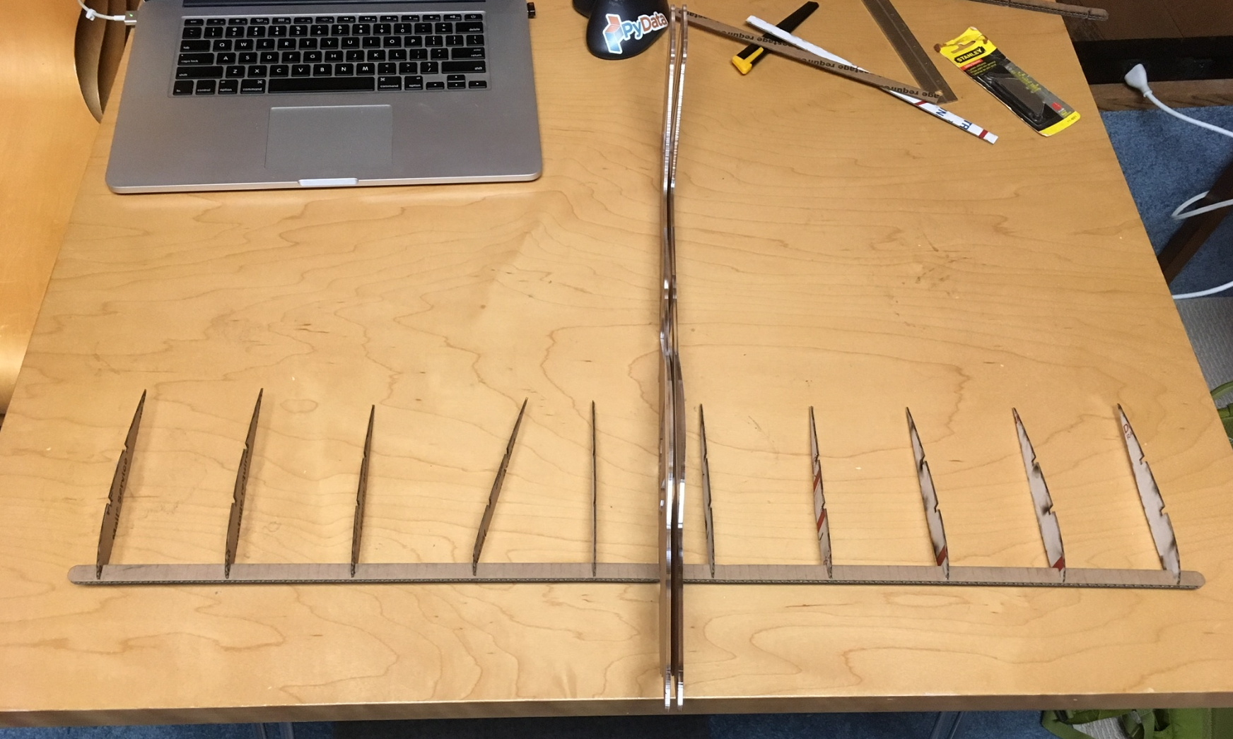
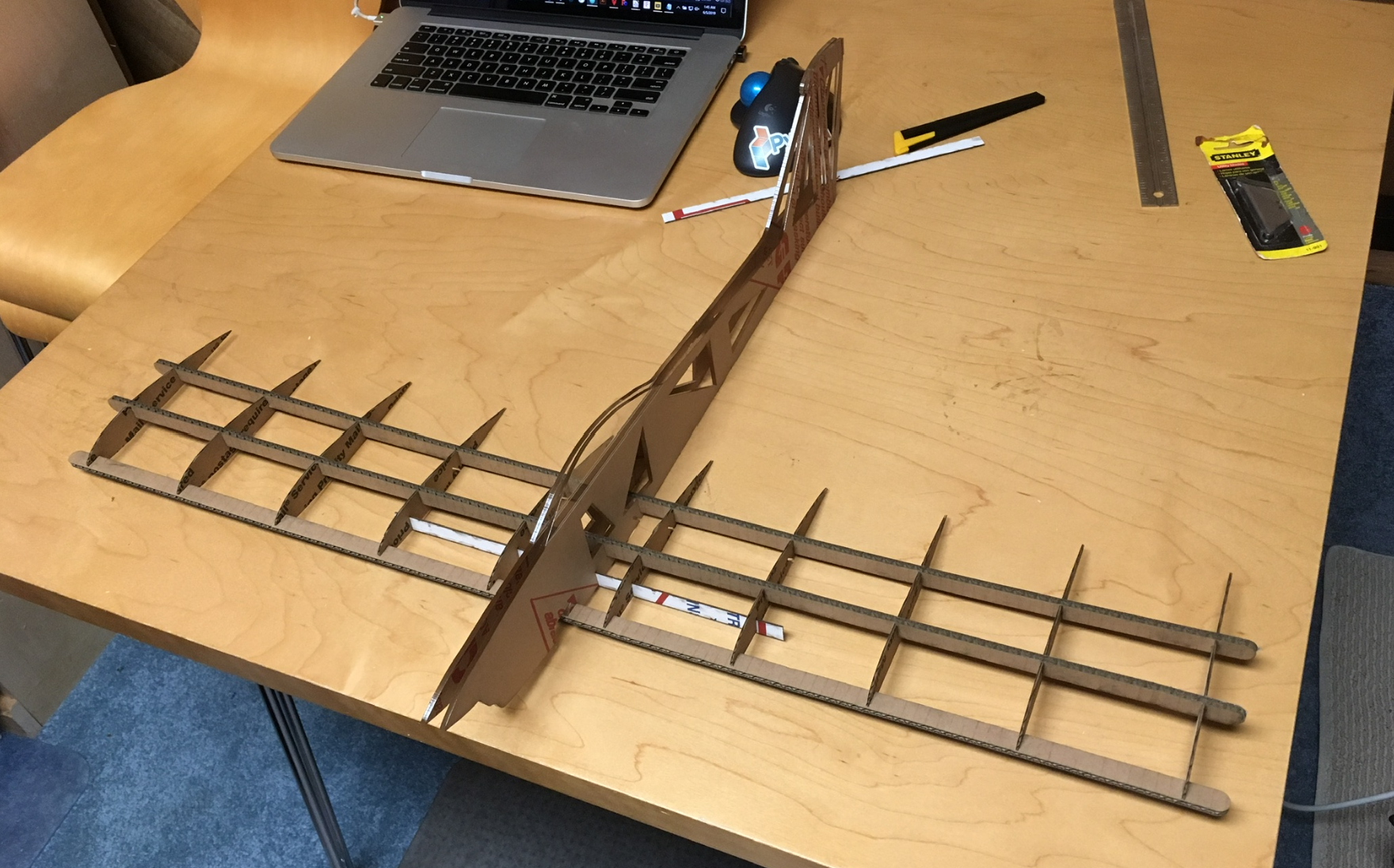
Horizontal Stabilizer
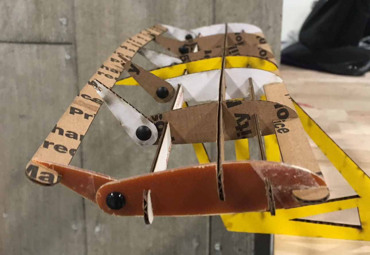
After disassembling the current stabilizer, the first step is to
assemble the elevator by attaching all the CNC'ed elevator foils
to the elevator trailing edge spar -- carefully.
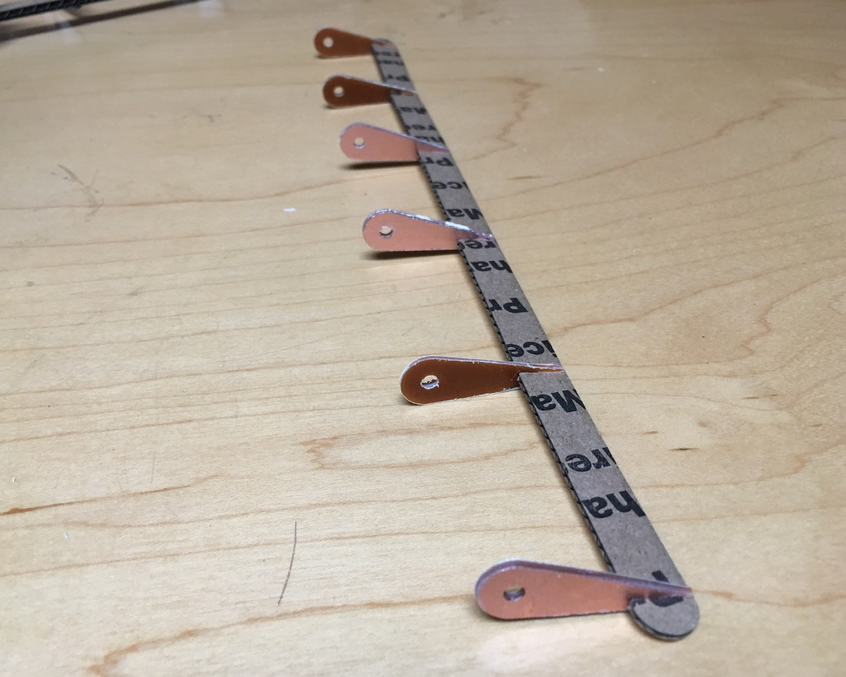
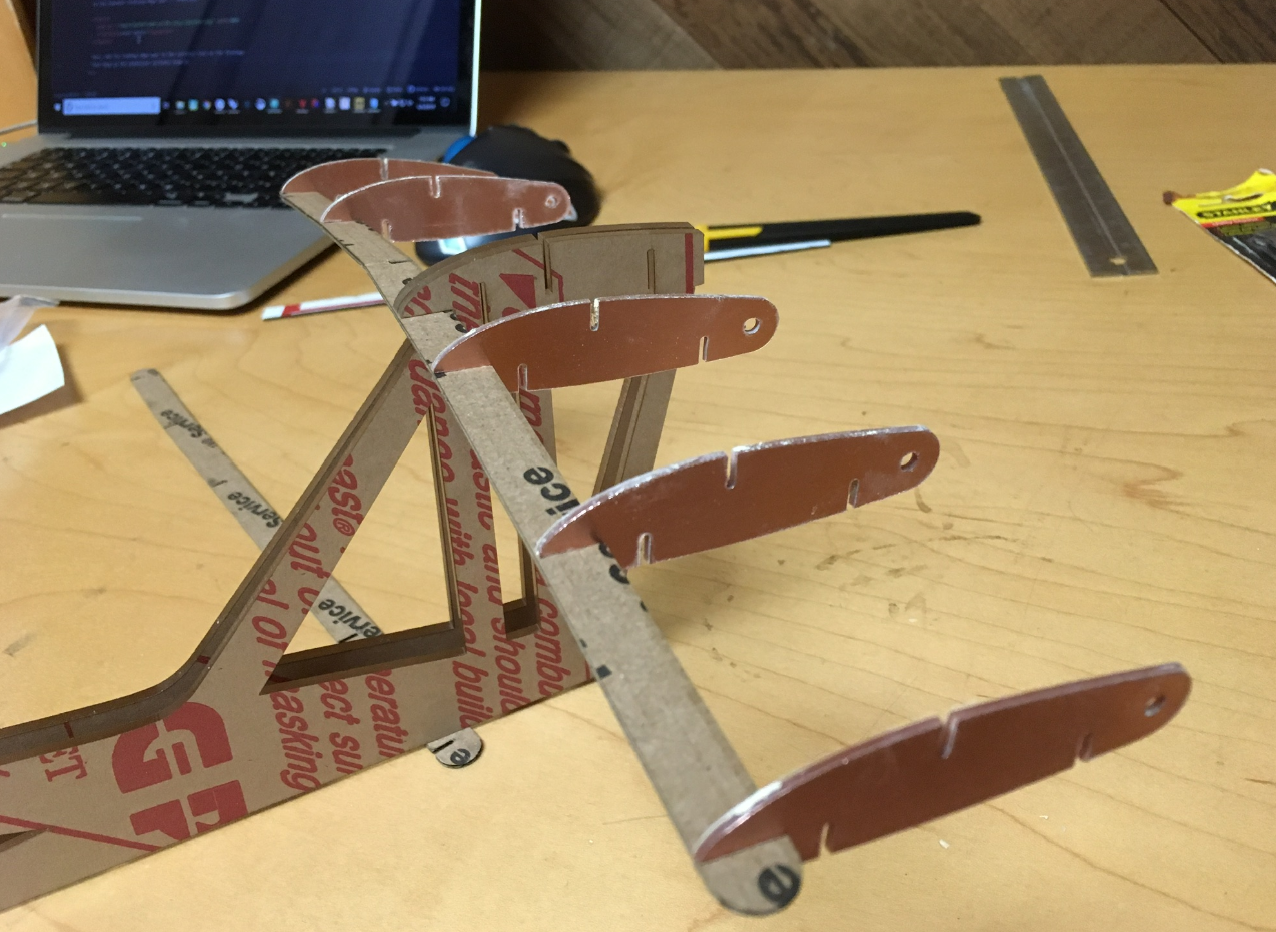
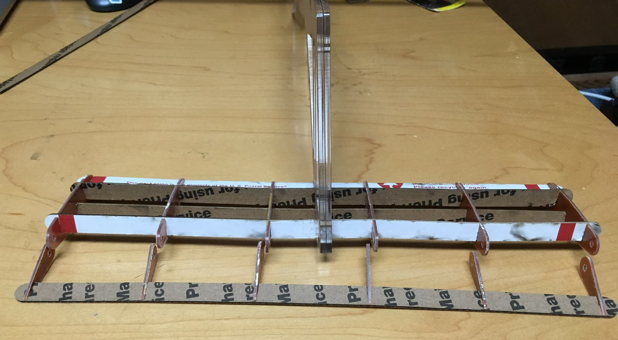
Last but not least is the landing gear.
Grab the 3D-printed struts, the brass axle, the stock wheels,
and clip them onto the landing gear spar. Done!
