TL;DR
- See embedded slides above.
- Everything below is a journal of my process in making them.
DAY ONE: Q&A, Plans & Panic
- Date: Wednesday 5/22/19
- Time: 8:30pm - 10:20 pm
- Location: Fluke Makespace, UW
- Goals:
- Ask Joshuas & Nadya some key quesitons
- Lay out a basic template for my pitch
- Get familiar with basic project requirements.
-
Steps Planned:
- Ask some quesitons after the Fluke Training.
- Hang back afer class and write things up while in Fluke.
- Steps Taken: Same as planned.
- Roadblocks & Impacts: none.
- Satisfaction (1-5): 4 (feel like I have a good handle on my project, anxious/eager to order rivents form McMaster Carr ASAP)
Haven't done a deep-read of the final project requirements yet, but I have some basic ideas.
-
It's gonna be an airplane. Probalby a static model,
not flying. Some airplanes are literally flying wings:

Northrop N-1M Udvar-Hazy Demilio~commonswiki assumed (based on copyright claims). - No machine-readable source provided. Own work assumed (based on copyright claims)., CC BY-SA 3.0 , wikimedia , wikipedia article. - Lots of laser cutting. Really emphasize the wing framework. All the spars and airfoils I'm good at, but more intricate.
- Some amount of stock parts. Probalby 3d print or maybe mill engine cowls, canopies, propellers as necessary. Maybe wheels from an hoppy shop; maybe a model with "retracted" landing gear.
- What if the whole model came from thingiverse? That's how I'd do a scale model. But instead of 3d printing, I'd "slice" it and do a bunch of lasercutting.
Asked Nadya a question about stock parts.
Can I base everything off a thingiverse model?
Yes, as long as I show some creativity in how I manufacture. Don't just 3D print it.
Asked Joshua some questions:
I'll probably incorporate my fowler flap, but it's gonna be really small. what kind of stock parts/fittings can I use in place of the rivets?
Yes, McMaster Carr has push rivets down to 0.063 inches. should be able to scale down my Homework 4 Fowler Flap linkage to itsy-bitsy, and use Bantam/FR1 instead of lasercutter/acrylic.
I want to "cheese" my airfoils -- cut out a bunch of triangular holes so
it looks like a truss instead of a solid piece (below). Does Rhino or
OnShape have functions to do this automaticaly?

Joshua didn't think they did.
I saw a tool in Rhino, that looks like it can automaicaly cut slots for the kind of airfoil-meets-spar joints I like to do. Do you know about those?
He doesn't, and after checking Rhino and Grashopper and OnShape, I can't find the tool either. I no longer believe it exists.
Before I sign off and git-commit/push for the day, Imma scan the actual project requirements real-quick. The only real constraing is to use at least four techniques.
- lasercutting wing and other framing structures/
- 3d printing cowl/nose cone
- casting canopy.
- mechanism flaps and/or other control surfaces
DAY 2: What the Fluke?
- Date: Friday 5/24/19
- Time & Place:
- 5-6pm @ Fluke
- 8:20-9:15; 12:30-12:47 @ home
- Goals:
- Get woodshop training @ Fluke
- Figure out when I can get trained for ShopBot and other CNC's
- Measure my material so I know how big my model can be
- Check if MILL has a vacuum former
-
Steps Planned:
- Take notes at Fluke & MILL by speaking into my phone and emailing myself.
- Write everything up at home
-
Steps Taken:
- Spent mrore time than I thought I would tuning up my html template
- The rest went as planned
- Roadblocks & Impacts: none
- Satisfaction (1-5): 4 Disappointed about Fluke's reduced hours & lack of training opporutnities, but I think I can work within these constraints if I'm careful.
Fluke Woodshop Training & Staff Discussions.
Fluke is almost a no go. No weekend hours this quarter (well, they're open Sundays but no staff to help or supervise.). They close at eight. I could maybe cram in a two hour print shop after work, practically need PTO and show up at 2pm to do anything useful.
CNC ShopBot: No training available this quarter so ShopBot is a no go. The other CNC is are a possibility if I have your tool pathing set. Even then, would have to do it with a staffer which means it has to be a weekday evening. Available CNC's:
- ShobBot: Unable to train for this one.
- Tormach PCNC 440Might be able to use this under supervision.
- RolandCan't figure out what model of Roland this is.
Laser cutters:
-
Red Universal laser systems:24 x 48 inches Yellow universal laser systems
45x60 cm Practically half the size of the ones at the Mill.
Q&A with Fluke Staff Confirmed I can start long-term/overnight print jobs and pick them up the next day. If I use fluke at all, it will probably be for bigger and more reliable 3-D printers, as well as the vacuum former.
MILL Visit
Reconfirm dimensions of my cardboard
- Trifold is 36 inches.
- Monitor box is about 40 inches.
- Priority mail is 20 1/2, with middle part at 14 inches.
Okay, So ...
- Biggest wingpan & fuselage length I can make is about 39 inches.
- Wing chord (based on prioirty mail cardboard) is around 14 inches.
- I'll probably still use the MILL for most stuff, but Fluke for vacuum forming and perhapse 3D printing.
Other Thoughts
I just-might make a flying model after all, ruberband-powered. I could do a basic plane with mulitple wings, based on multiple NACA airfoils, that you could interchange. That would (what feels like) a stronger intended use than "static model to look at" or at best "teaching tool to explore aicraft internals and how control surfaces move." I'll probably give that some more thought another day.
DAY THREE: Pulling Together an Actual Pitch
- Date: Sunday 5/26/19
- Time: 4:34pm - 6:45pm; 7:49pm - 9:36 pm
- Location: Home (Sammamish, WA)
- Goals:
- Get my main idea into slides for a turn-inable pitch.
- (Stretch) maybe play around with an alternate idea or two.
-
Steps Planned:
- Go thru the slides, adress the pitch requirements.
-
Steps Taken:
- Filled in the first slide with overall concept & BOM.
- Use github.com's Project, Milestone, and Issues features for the schedule.
- Back to slides, set up slide 2 with schedule, tasks, and contingency plan.
- Roadblocks & Impacts: Not much time avaialble, probably need to trim back my plans.
- Satisfaction (1-5): 3 Getting more nervous about how much there is to do and how little time left.
4:34 pm All Right, Let's Get this Session Started
Okay, imma start by googling up some images for the cover slide. Probalby do a "collage" with a basic aircraft, plus callouts for cardboard lasercutting, 3d printing, etc. I'm zeroing in on a Piper Tomahawk as my aircraft of choice, because ..
- Simple rectangular "heshey bar" wing
- Wing on bottom/tail on top for easy attahcment
- Bubble canopy
Here's an interesting hit. Plans for an old-school balsa model, but with lots of cross-section info on wings, tail, fueslage that I could use.

5:33 PM I'm pretty happy with the overall concept, materials, etc on my slide 1, now I'm starting to think about timelines.
Imma use github issues and github milestones to lay out my timeline. Started with the Order Parts milestone since that's one of the the first things that needs to happen; now imma pivot to "working backwards" by laying out the last milestone and figuring out what needs to happen before that; then keep working up the chain.
Managing Nights and Weekends
Okay, laying out github milestones Has been very illuminating. Dates are starting to "crash into each other" as I think about how much time I need to set asside for 3D printing vs. laser cutting vs. CNC -- not to say how many "pure cadding" days I'll need.
A few major things are starting to jump out:
- There's only one left in the schedule. By the time I get to Saturday June 1 all the CAD, lasercutting, and cardboard assembly needs to be complete. I'm going to need all the weekend time for lon-lead fab jobs like vacuum forming and 3d printing.
- I need as few unknowns as possible. This means sticking with the materials I know - science fair trifolds and USPS cardbaords, so I don't need to do further thickness studies.
- Forget the Flaps and go with simple hinges for ailerons, elevator, and rudder.
- Screw It and Glue It instead of Clueless and Glueless
- Flat Fueselage Less cadding and faster laser cutting, though I'd need to rethink my 3D printing and vacuum forming. Maybe save that for wing tips.
7:49 pm Getting Back to Taming the Schedule
Okay, in the pre-dinner session I figured out there's only one full Saturday and Sunday avaialble for this project, and that I need to have all the CAD ready so I can spend those day days on long-lead Fabrication tasks. I've also got some contingencies identified. Now I feel like pivoting and doing "contingencies" first. In other words, an agile-style iterative plan.
- Get the Inevitable Stuff Out fo the Way First. No matter what contingencies I take, there will definetly be wings, horizontal stablizer (the small wing-like thing in the back), and hinges for ailerons and elevator. If those hinges involve push rivets and some CNC/FR1 parts, we've got Lasercutting, CNC, and mechanisim design done already. If I go with Grashopper, for the airfoils, I have parameteric design too.That's four fabrication techniques(ish) already.
- Flat Fuselage Before Full. Have a flat fueslage ready for lastercutting before doing anything with 3D cowls or vacuum formed canopies.
- Slide in the Sliding Fowler Flaps. Adds lots of coolness, re-uses lots of what I did in the past.
- 3D Print Some Airfoil Tips. Easy way to bag one more fabrication technique. Can use them whether I go flat fuselage or full 3D.
- Square Away Those Stock Parts. Wheel's, prop, spinner -- makes the model look finished no matter what.
- Finally a Full Fuselage. If I make it this far and there's still time left, I can CAD and lasercut framing for a full 3D fuselage. Hand-in-hand with that would (probably) come a 3D-printed cowl and vacuum formed canopy. So if all that's actually gonna happen, and I need the weekend for those long-lead items, I'd need to be CAD-complete on this by Friday.
9:36 pm Feeling pretty good about my slides, I think I've met the minbar for the assingment. Tomorrow I'll sunch up my github milestones and get to work with some parts procurement and initial cadding.
DAY FOUR: Order Some Parts
- Date: Monday 5/27/19
- Time: 9:30am-12:38pm; 1:41pm-2:37pm; 3:23pm-4:52pm; 5:06pm-6:20pm; 7:48pm-7:56pm; 8:49pm-9:44pm
- Location: Home (Sammamish, WA)
- Goals:
- Synch up my Github Milestones with my Project Pitch
- Order Parts (or at least confirm shipping)
- Steps Planned:
- Synch up my Github Milestones with my Project Pitch
- Check availability & shipping times of FR1 on Amazon
- Order the FR1
- Check availability & shipping times of rivets on McMaster-Carr
- Do "Just-enough" cadding so I'm reasonbly sure what rivets I need
- Order the pins
- Steps Taken:
- Synch up my Github Milestones with my Project Pitch
- Check availability & shipping times of FR1 on Amazon
- Touch up my slide #2
- Explore the flying wing concept again.
- Confirm fastner sizes based on flying wing. Lots of do-overs and deep-study of balsa wood plans I found.
- Figured out my assumptions were wrong, recomputed fastener sizes based on Acrylic and FR1 instead of USPS cardboard.
- Roadblocks & Impacts: Worried about lead-times for ordering pars.
- Satisfaction (1-5): 3
Synching up my github Project, Milestones, and Issues, was pretty straightforward. The sheer number of tasks is making me want to trim my project concept even more ... maybe pivot back to that flying wing concept.
Checking Amazon & McMaster-Carr proves that I need to order parts today if I want to have them on time. The FR-1's a no-brainer, but it's hard to even guess at the right pins until I do some initial cadding.
What if I Just Did a Flying Wing?
I have a pretty good handle on what's involved with the Piper Tomahawk concept - start with 3D wings and flat fuselage, move on to 3D fuselage if time allows. What would a Northrop N-1M involve?

Northrop N-1M Udvar-Hazy
Demilio~commonswiki
assumed (based on copyright claims). - No machine-readable source provided. Own work assumed (based on copyright claims).,
CC BY-SA 3.0
,
wikimedia
,
wikipedia article.
Lesse ....
- Complex wing (swept and tapered).
- Could use one of my homework 6 canopies.
- Stock part props & landing gear.
- Hinged control surfaces, now fowler flaps.
Found some plans, so maybe not as hard ad I'm thinking?

Encouraging; let's cross-check against the final project requirements.
| Requirement | Notes |
| fab technique 1 | lasercutting (frame) |
| fab technique 2 | CNC (canopy, hinges) |
| fab technique 3 | casting (canopy) |
| fab technique 4 | 3D printing (landing gear struts) |
| 2D designs | cardboard frame |
| 3D designs | canopy, landing gear struts |
| moving parts | elevons |
| additive fab | 3d-printed landing gear struts |
| subtractive fab | CNC canopy mold |
| stock parts | push pins, propllers, wheels |
Looks feasible, could very well be easier than the Tomahawk. Seems to hit all the features I'm looking to do, with fewer parts to manufacture. I could either "trace" the pdf plans, or do a parametric approximation by modifying my wing spar generator to support the angled slots required by the swept leading edge. Then I'd use the Grashopper airfoil generator to approsimate the various airfiols form the plans. So what's thing going to entail?
-
Spars for Swept Wings.
- Start with the homework 3 parametric wings spar, set the slots at an angle.
- Figure out a way to fuse two spars to make a V.
- Use science fair trifoil cardboard.
-
Airfoils
- Start with the pdf plan, pull in one airfoil into Rhino as a reference image.
- Use the Grashopper airfoil generator to generate foils that more-or-less match.
- Use USPS cardboard.
-
Control surfaces
- Trailing edge is straight (thank goodness) so it's no different than what I have planned for the Tomahawk.
- I don't think N-1M had actual fowler flaps, but I could do them "just for show."
- Also an opportunity for "split flaps" used in flying wings.
-
Landing Gear
- Start with the 3D prints from assingment 3, since we're using the same USPS cardboard.
- Re-use the slot, but combine with something that can accomodate wire landing gear avaialble at hobby shops.
-
Propeller Farings
The props can be stock parts; the yellow fairings that
support them could be tricky.
- Use specialized airfoils for the basic shape
- Lay a 3d-printed "adaptor" on the top that has an assingment 3 style groove for the airfoil side and a round hole on the other side for attaching the prop.
- Stock Parts If I'm gonna do this, I should by props & landing gear asap so I can work out how I'm gona do 3D printed adaptors.
- Canopy Reallly hope I can reuse one from assingment 6.
So I think the flying wing might be easier, but I'm not ready to refactor my project plan just yet. Probably noodle with some swept wing desings and scanned planns, thoug.
1:41pm-2:37pm Playing With Plans
One of the big unknowns is how the interplay between the pdf plans that cad tootls is gonna work. So let's try that.
- Download the Plans. Came as JPG, so far, so good.
- Isolate an airfoil. Open in Paint.net (Right-click/Edit in Win10), select an airfoil from the overall plans, copy.
- Add to Illustrator Paste the Airfoil into Adobe Illustrator, Resize the arboard to be just-big enough for the foil, rather than the entire 32x22 inch lasercutter bed.
- Vectorize in Illustrator Select the aifriol, then Object Menu > Image Trace > Expand. Export as DXF
- Pull into Rhino Pull the DXF into Rhino, align so it faces same direciton as Grashopper Airfoil generator. Generate a foil, try to get it to match.

3:23pm - 4:52pm Basic Sizing
Still need to order those parts. Before I can know (roughly) what size pins I to order, I need an idea of how big this thing is gonna be. The original plans are "chopped" such that they don't show the full wingspan.
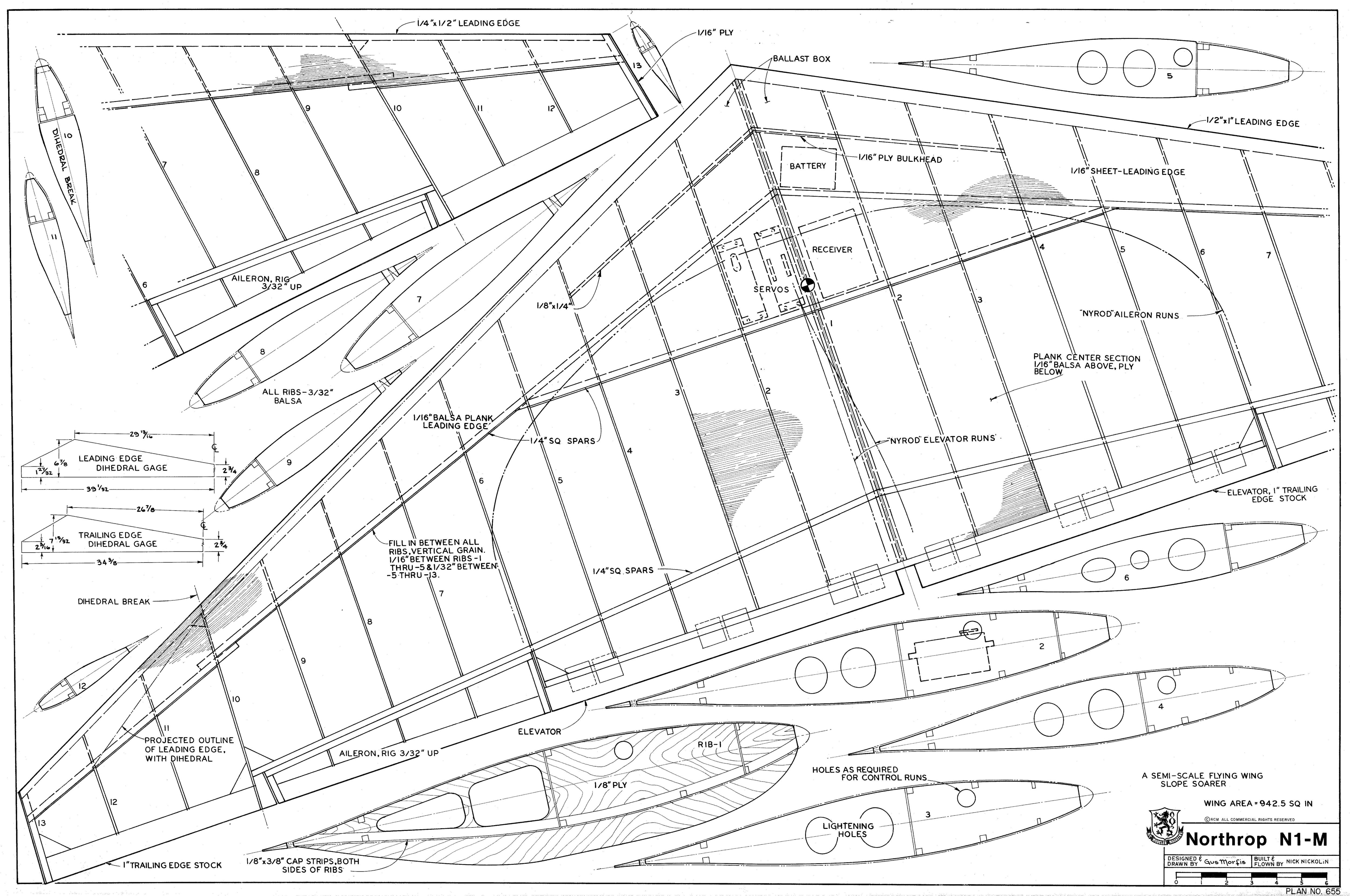
Import into Adobe Illustrator, copy, crop, rotate, scale, and ...
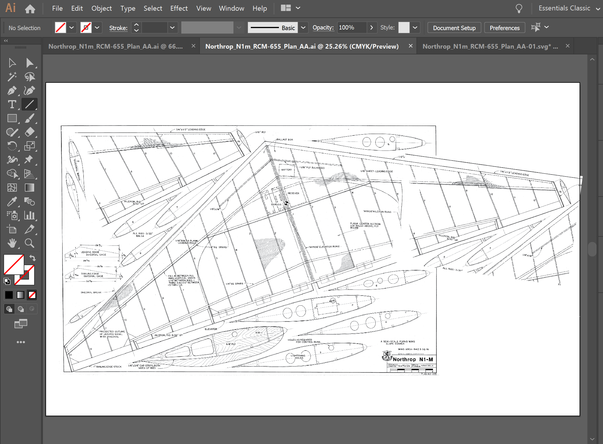
Now I can take some mesurments from illutrator. By just drawing a ling along certain features and reading off itss length.
- Half spar lengh of 439 mm
- Max Airfoil chord length of 235 mm
- Midway Airfoil chord length of 154 mm
- Small Airfoil chord length of 90 mm
- Tip Airfoil chord length of 45 mm
Next, I'll grab that airfoil I made earlier, set the chord length to 154 mm, import into OnShape, and see if I can scale my fowler flap mechansim from Assingment 4 to fit. Nice, OnShape interpreted my 154 mm airfoil as 8037mm.
Wait. I'm overthinking this big-time. I can just go to adobe Illustrator and measure there. Duh. Zoom in on the plan in Illustrator. Aileron lies between Airfoils 6 and 10, with 10 beign the smallest.
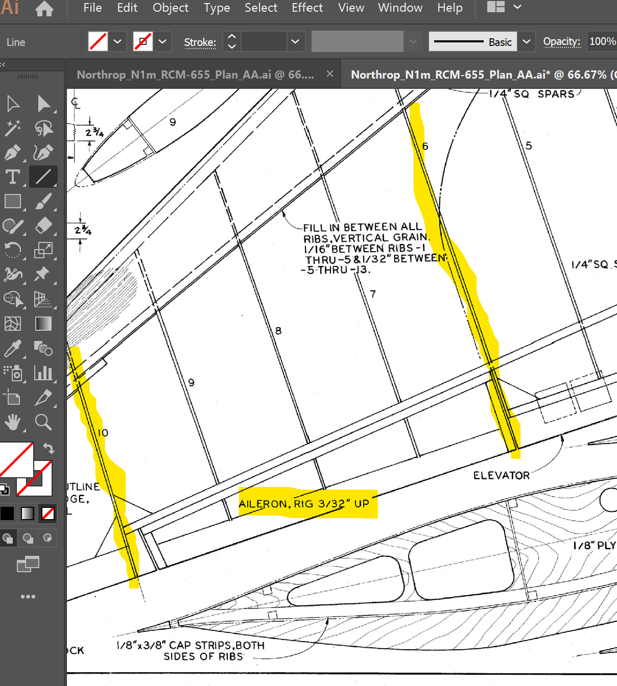
Find Airfoil 10 aond the plan, zoom and measure. Draw a box representing a pin, get 0.08 inches. That's the max hole size. The airfoil is about 0.17 inches thick at this spot, so that's the max head diameter.
Going through my notes from Assingment 3, my calipers said the USPS cardboard was 0.08in thick. In Assingment 5, my FR-1 was 1.65mm which comes to 0.06496063 inches. In Assingment 4, I made a fowler flap linkage with no more than two layers per pin. So I'm looking for:
- Head diameter of 0.17 in.
- Hole size of 0.08 inches or less.
- Material thickness of 0.145 inches.
Now I'm ready for McMaster-Carr!
5:06pm - 6:10pm Shopping Spree ... or not.
All right, I've got my masurements (finally) now I can hit McMaster-Carr and see how close I can get. Looking over the filtering choices, it's going to be all about hole size, with material thickness a second priority and head diamter third. Dialing in the filters on the left-hand pane. Filtering for ...
- Hole Size 0.064 - 0.094
- Material Thicness up to 0.249
- Head dimater 0.1 ro 0.2
It's also worth noting that the most senstive measurment is material thickness. If I need a larger hole or head size, I can just slide the hole further forward where the airfoil is always thicker. If the rivet wants a thicker material, I can shim it with thin washers or something. Not much I can do if I exceed the rivets max material thickness though. Factoring them all together I get ...
The Click-Lock Shank 91020A491 looks like it will be my best bet. I'll prorbalby also get some Arrow Shank 90218A216 for variety.
6:10pm - 6:24pm Yet Another Gut Check
Am I really going to use cardboard airfoils with my moving parts? They performed so poorly in the cardboard prototype stage of assingment 4. If an Airfoil's going to have a rivet in it, it should be made of Acrylic. If it's Acrylic, it should be the same thickness I used in assungment 4, since the thinner stuff breaks easily. Gonna need to recalculate my material thickness again.
7:48pm-7:56pm; 8:49pm-9:44pm Recalibrating for Arcryillic Airfoils
My prior McMaster-Carr shopping assumed I'd be fastening FR-1 linkages to USPS cardboard. I should really use 1/8" arcryillic for airfoils that will have rivets in them, or maybe FR1 for them too. All the airfoils that aren't involved with moving parts can still be cardboard.
8:49 pm What's the biggest airfoil I can make with FR-1? The standard size is 100 x 70mm, which yields a max chord lenth of about 122 mm according to Pythagoras, so trim it to 118 mm to allow some slop on the ends. Only the a irofils near the tips are that small, so airfoils that connect to flaps and ailerons will need to be Acrylic. The ailerons and flaps themselves? Those could be FR-1.
What will my linkages look like? The simple "hinge-type" linkages for ailrons, elevons and rudders will involve a "wing airfoil" made of 1/8 inch Acrylic connected to a small "control surface airfoii" mae fo FR-1 with a single pin. Fowler flaps would also involve a 1/8 inch Acrylic "wing airfoil" connected to an FR-1 "flap airfoil," but there would be multiple FR1 linkages in between. Pulling up one of the images from Assingment 4 ...
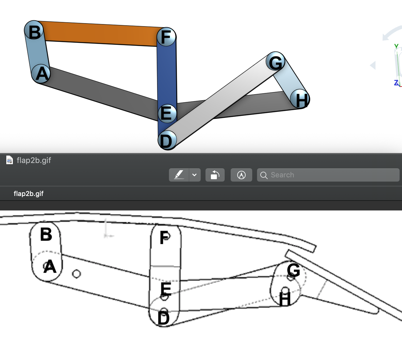
Checking each Pin I have ....
Ok, that confirms every linkage is either FR1-FR1 or FR1-Acryllic; no other combinations. Now I know I'm looking for mmaterial thickness of 0.13 and 0.19 inches (unless and until yet another brain burp convinces me otherwise).
Now Let's go back to McMaster-Carr.
Okay, I'm liking this. Two choices for each thickenss. I'll be committed to Click-Lock shanks for Acrylic-to-FR1 connections, but will have a choice between Click-Lock and Arrow for FR1-to-FR1. Now I'm gonna take a break, think things over then place the order if I'm still feeling good about it.
10:15-10:40pm Order the Parts (Finally)
FR-1 will arrive from Amazon Thursday May 30; Push Rivets will arrive Wednseday May 29. I'll be ready to all-day-fab-days on Saturday and Sunday.
DAY FIVE The Wing's Not The Thing; Turn Back to Tomahawk
- Date: Tuesday 5/28/19
- Time: 9:05pm-11:28pm
- Location: Home (Sammamish, WA)
- Goals:
- Finish the Pitch
- Start Some Cad
- Steps Planned:
- Finish the Pitch
- CAD up the basic wings
- CAD up a flat fuselage
- Steps Taken:
- Finish the Pitch
- Find some plans, import into Adobe Illustrator.
- Assign some dimentions, export to Rino.
- Got a basid fuselage outline & a wing profile kinda.
- Roadblocks & Impacts: Been thrashing between Flying Wing and Tomahawk. Need to make a decision & stick to it. Worried about really being ready for 100% fab ty Saturday monring.
- Satisfaction (1-5): 3 (worried about deadlines.)
Finish up Slides Already
Updated BOM & Sourdinb shedule to reflec t part I alrready have on oder. Tweak Techniques & materials to hype up parmateric wings and 2D vs 3D CAD. Also added a third slide for the wing idea. That should do it.
On to CADDING
Figure out the Main Dimensions Similar to what I did for the Northrop Wing. Constrain it to about 32 inches wide so it fits on either laser cutton in the MILL, and also one of them at Fluke. So really that's 30 inches max to allow some slop at the edges. Now, pull those plans into Adobe Ilustrator so I can figure out dimensions of the rest of the parts.
Find a Plan to Make a Plan As with the Nothrop Flying Wing, Imma need some plans. A bit of googling brought mulitple promising candidates, but my fave once again came from outerzone.co.uk again.
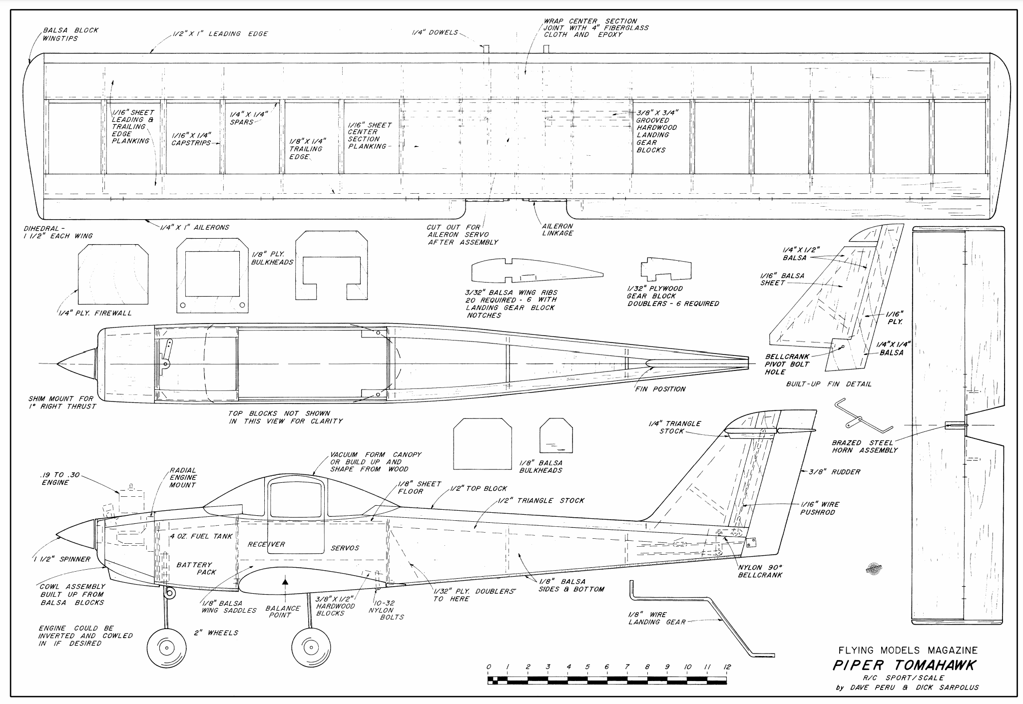
Download the plans as native PDF, open Adobe Illustrator and with a blank 32x22 inch document, impor the PDF and ...
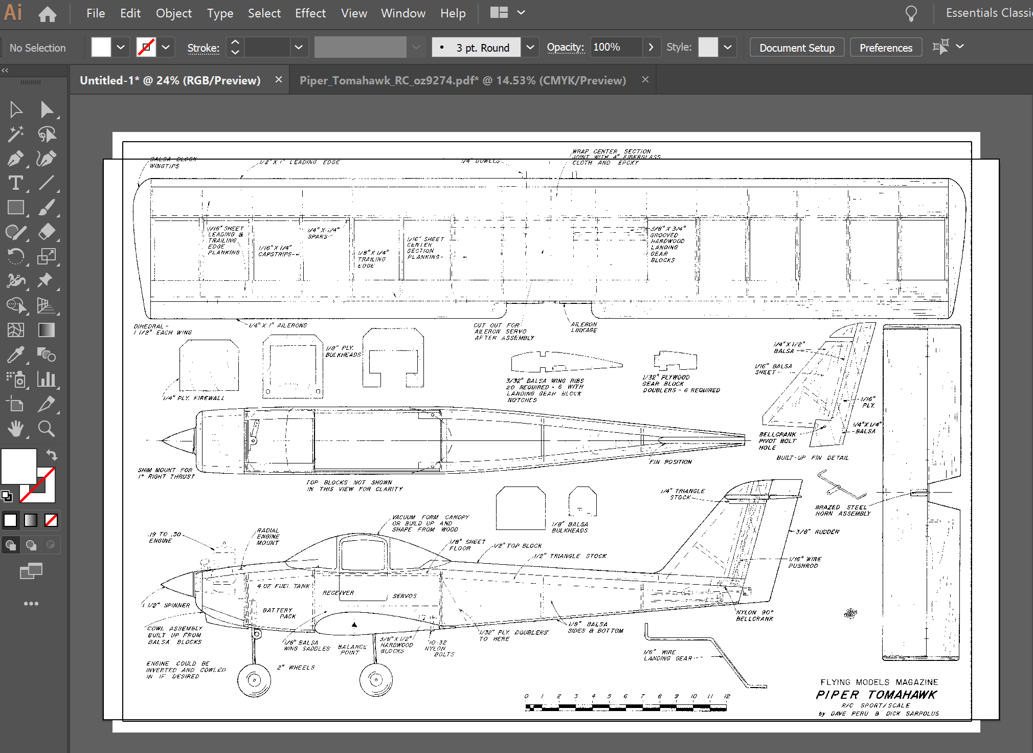
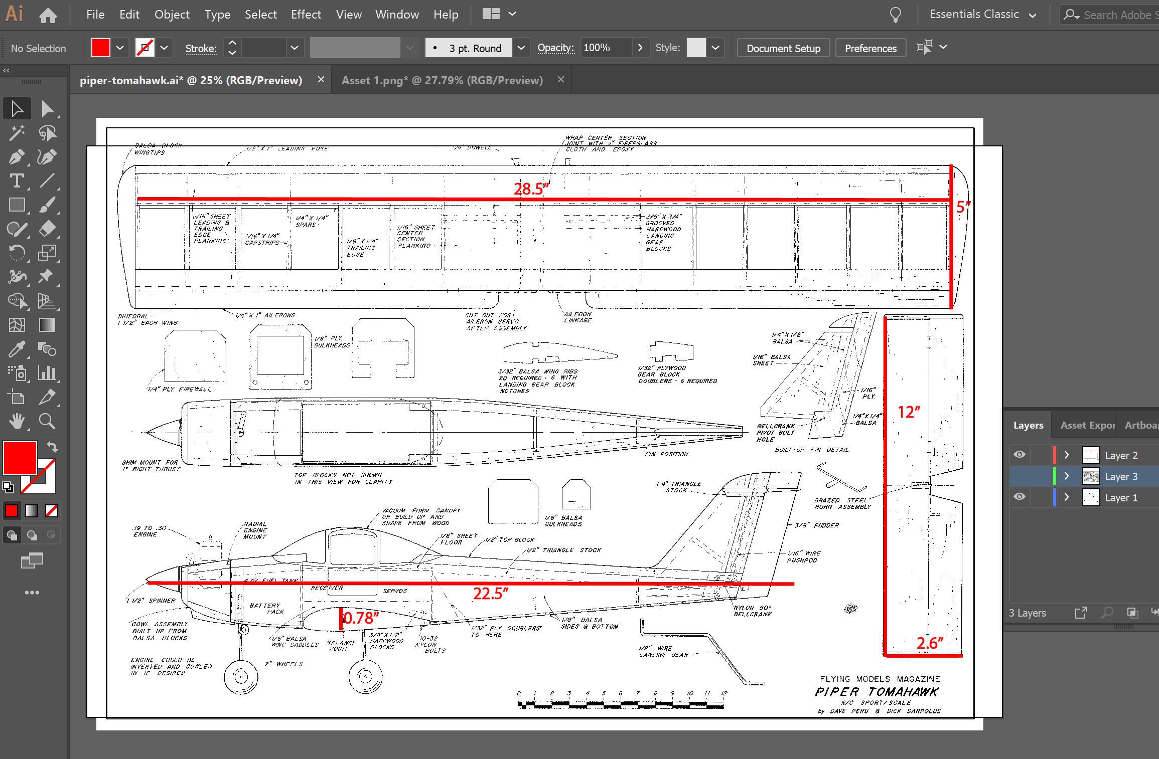
Add some lines, measure, and markup. Use Illustrator's layering features to isolate dimensions form the drawing.
Vectorize Using the same technique as for the Northrop wing, added the Tomahawk plans into Illustrator as an image. Then use Object Menu > Image Trace > Expand. Export as SVG (DXF wasn't availabe) this time. Pulls into Rhno just fine, where I can use control point curves to trace out the fuselage.
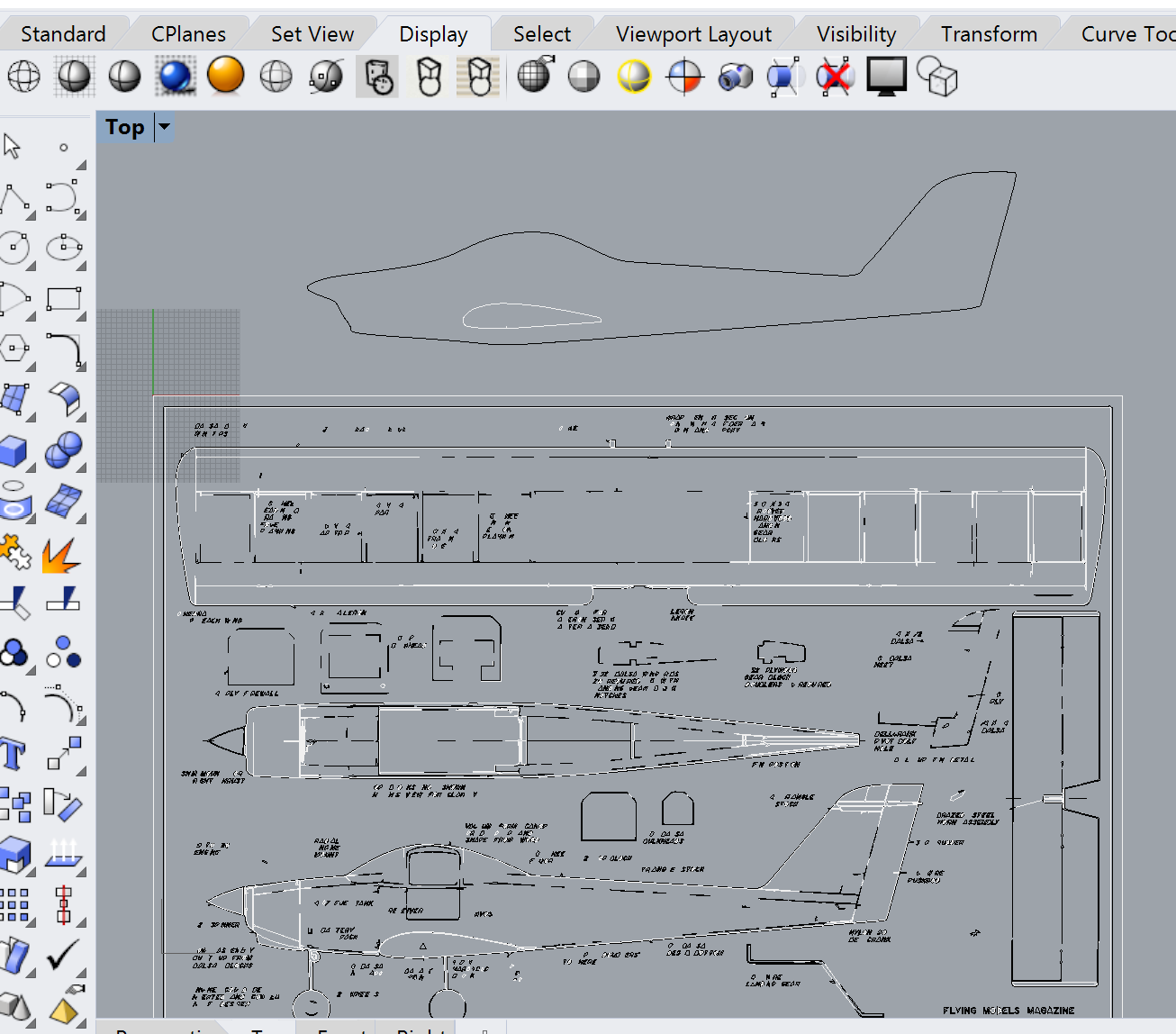
Settle Down and CAD a Wing
It's gonna be 28.5" span, 5" long airfoils 0.78" thick. Horizonatl stabilizer will b 12" by 2;6" with an unusually thick airfoil so I can make an elevator.