Leo's Assignment 4: Fowler Flap!
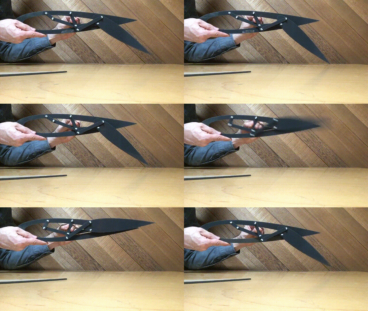
Here is all the documentation for assignment 4!

Here is all the documentation for assignment 4!
Available on github.com at https://github.com/LeoSalemann/LeoSalemann.github.io/tree/master/hcde598/hw04
Also see hw04-fowler-flap on Onshape
Hmm ... I wonder if I could make a wing flap mechanism?
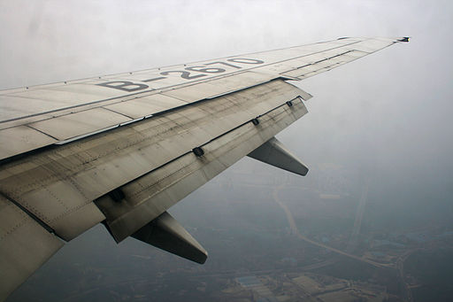
A bit of googling around lead me to a an RC Univers forum post Showing a mechanism that's deceptively similar to to Joshua's scissor linkage.

The post also references a 3D version on woodrel.com.
Bought the Acryllic at TAP Belelvue. Scoured east side craft shops for OOMOO, finally ordered it. Relly hope Vetco has FR-1 or I'm screwed.
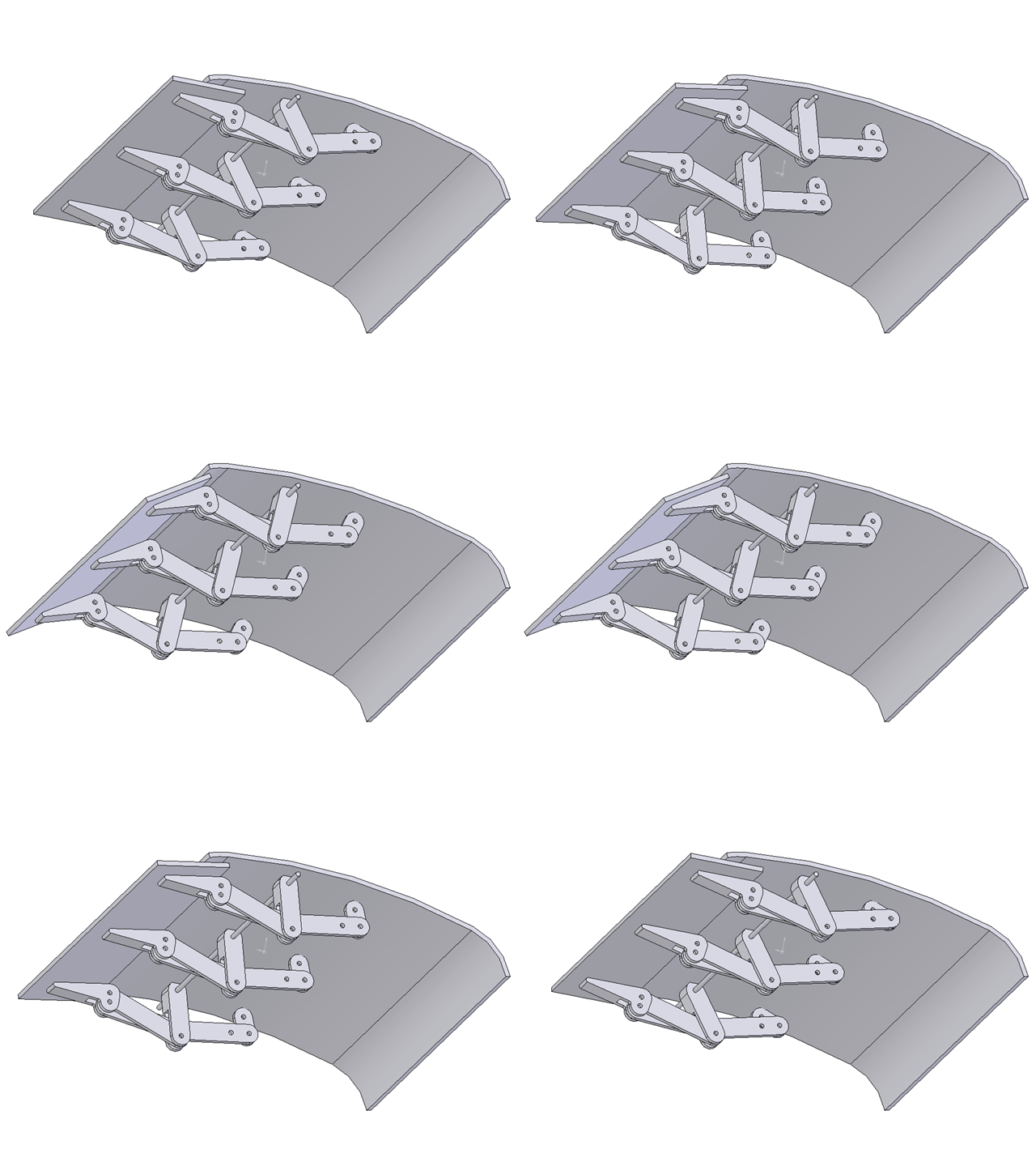
Started sketching the actual airfoil/flap assembly . The 3D gif was really useful for this.

I'm gonna have two airfoils, using the small one to cut a chunk out of the bigger one. The 3D gif helped me figure out that pins A and B will attach to the main airfoil (orange), G and H attach to the flap (blue) and everythign else is basically "free-floating."


I should cut this in cardboard first to ensure everything moves right before movig to Acryllic. Maybe OnShape motion will give me enough confidene.
Last night I was worried that this linkage would require too many "stacks" of struts & airfoils pinned togther. This morning I figured out I can cut out some spaces in the airfoils to accomoodate (red.)

Hoping to do some cutting tonight, but first gotta get smarter on OnShape. Start with Joshua's Class recordings. Yup, that definetly helped. So I think my course of action will be ...
Start with Joshua's, shrink it to AB and DF below. For now, add a "fake link" BF just for them to have something to "push against," and create a simple AE instead of the bent-line AEH.

Okay, I've got the link in my own OnShape document. No easy way to convert to sketch and/or scale it, so I'll have to rebuld. Start with the hole; it's 6.198 mm.
Build a new circle from scratch at the origin, set diameter to 6.198 mm. Copy/paste to create a second one. Set up a construction line between them. Add a "real" line underneath, to start the one edge of the linkage.
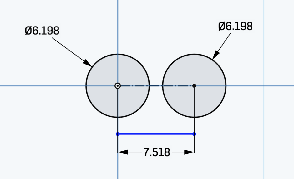
Copy/paste the blue "link edge;" add a consturciton line so everything can be the same distance from the rivet hole.
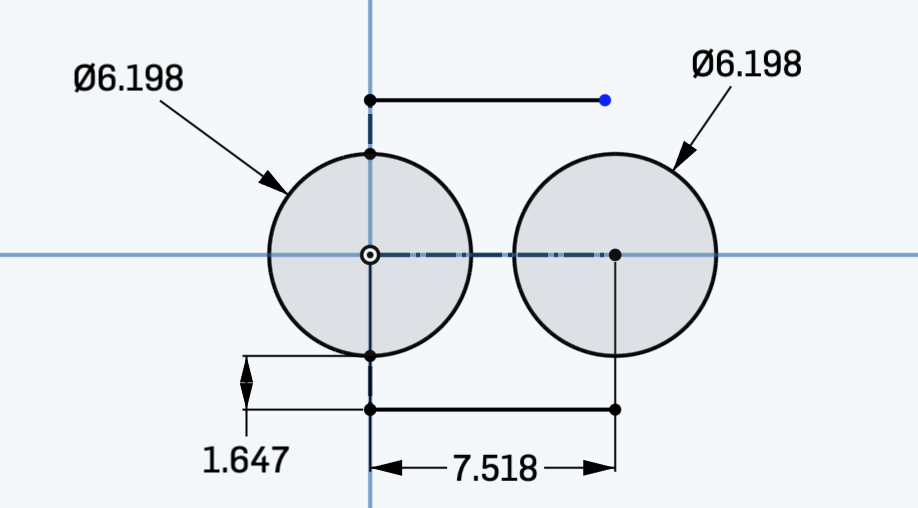
A couple more construciton lines, a pair of 3-point arcs, a generous sprinkling of "equals" constrains and ...
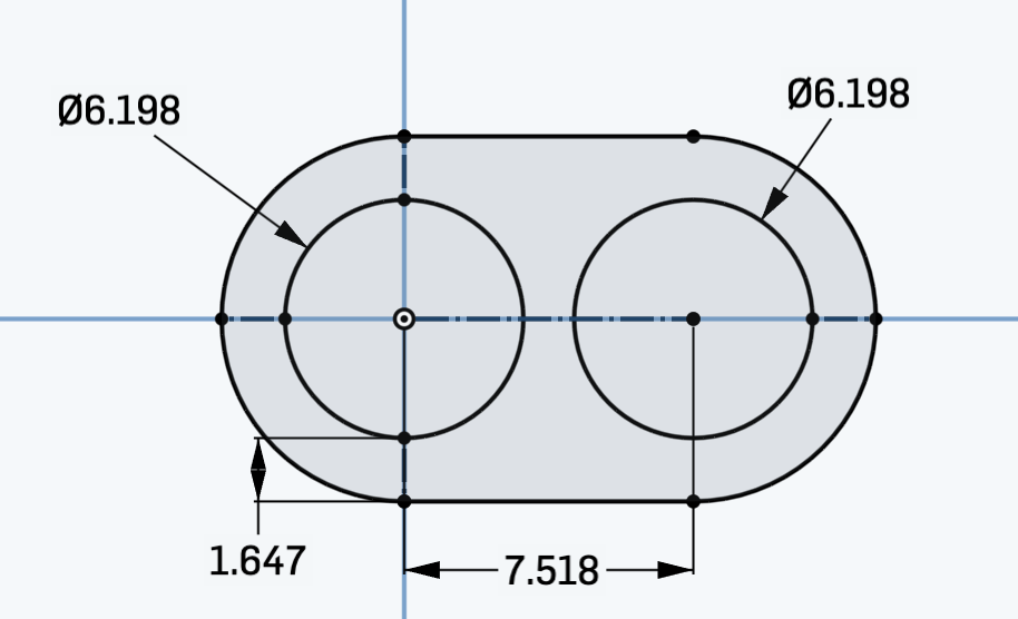
Now all I have to do is change the length (7.518 mm) to anything I want for the rest of the links. I can also change "hole to edge thickeness" (1.647mm) to get closer to Joshua's verison. In fact, I have Joshua's link in my document! I can just add some construciton lines and dimensions and ...

Back to Joshua's part, figure out the extrusion height. Looks like 2.381 mm.
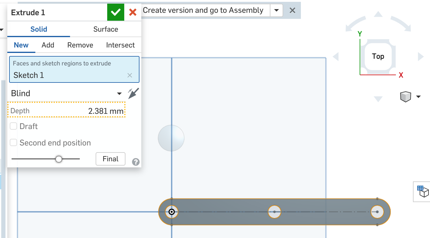
A quick visit to the Exrusion command, insert the part into the assembly, and ....
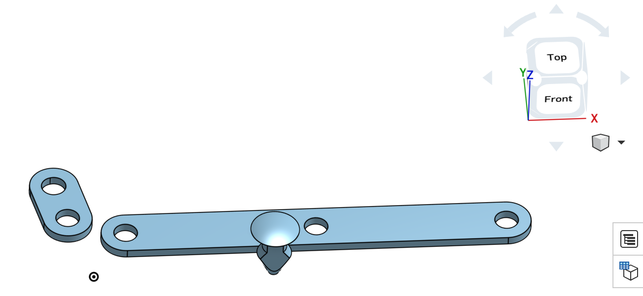
First, Imma copy/pasta a little miny part five times for a total of six. Then in Assemly mode, I'll insert and orient them. That'll give me some idea of how much each one needs to be stretched for the final fowler linkage. Okay, let's try this. Replicate one part at one lenght, arrange in Assembly View.
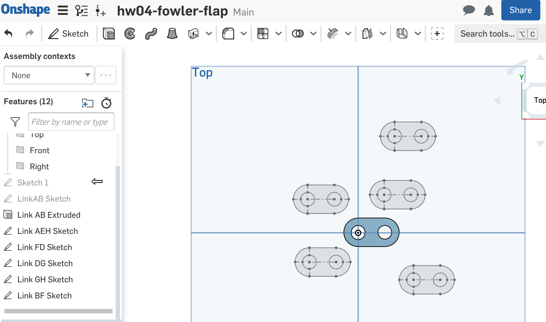
Now it's time to ...

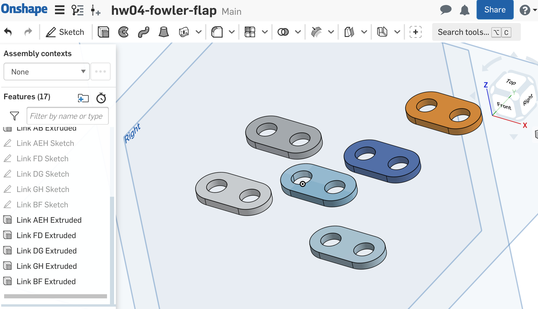
Time to pivot to Assembly mode, where I learned a valuable lesson about naming my parts. Arrange them to match the folwler flap gif, so all I have to do is scale. We'll use Link AB as the baseline, call that lengh 1.0.
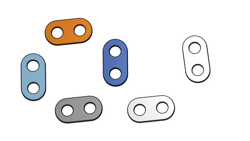

Easy,right? Eyballing things, Imma guess:
Y'know? This would be a good time to leverage OnShape's version control system.

Y'know what, I also res-scaled AB and GH to make them 10 mm long instead of 12 mm. Right then, back to Sketch mode, adjust one dimension on each link. Pivot back to Assembly mode, arrange the parts a bit, and ...
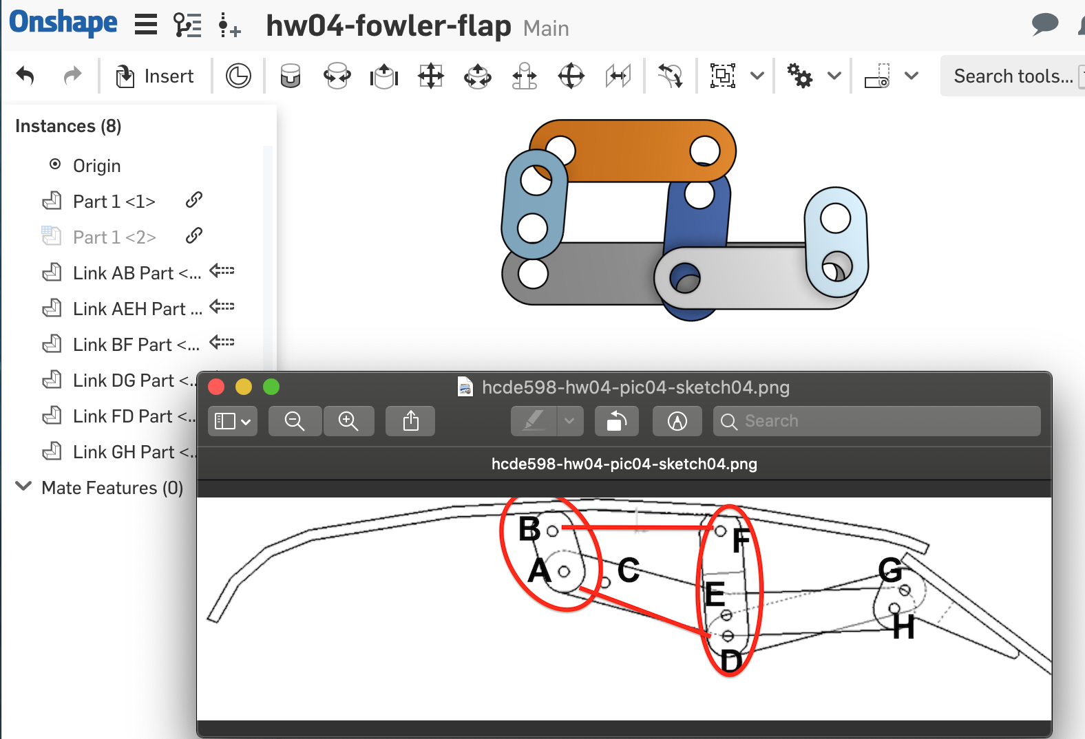
This one makes me nervous. Need to somehow "break" and "bend" Link AEH. Back to Sketch Mode. But first, capture another version.
Remove the main (60mm) length dimension constraint.ß Delete the lines entirely.

Add a couple new consturciotn lines to create the "bend." Add some dimentions to set the length of the "legs: and the angle between them.
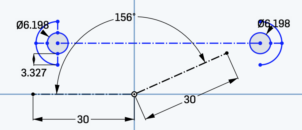
Move the circles, rebuild the arcs, add some more constraints. Now I have everything but the actual bent lines.
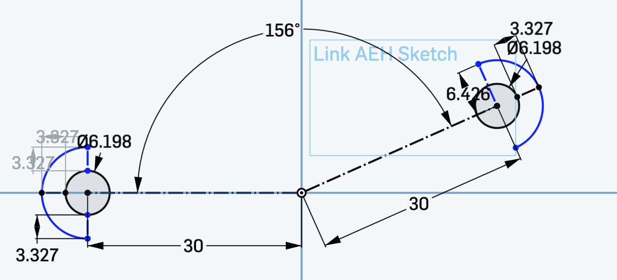
If all else fails ... MOAR construciton lines!
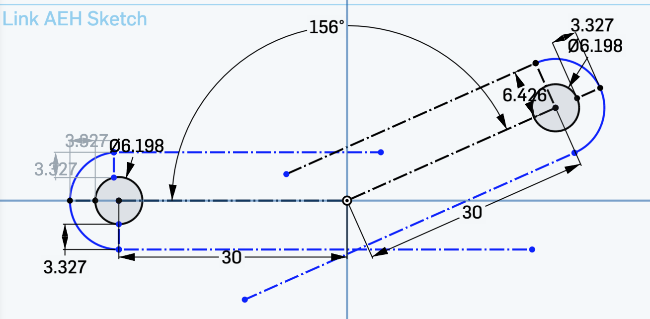
Cool! Onshape was smart enough to find where the constuction lines crossed, and to snap the real lines there! All I need now are a few more constraints.
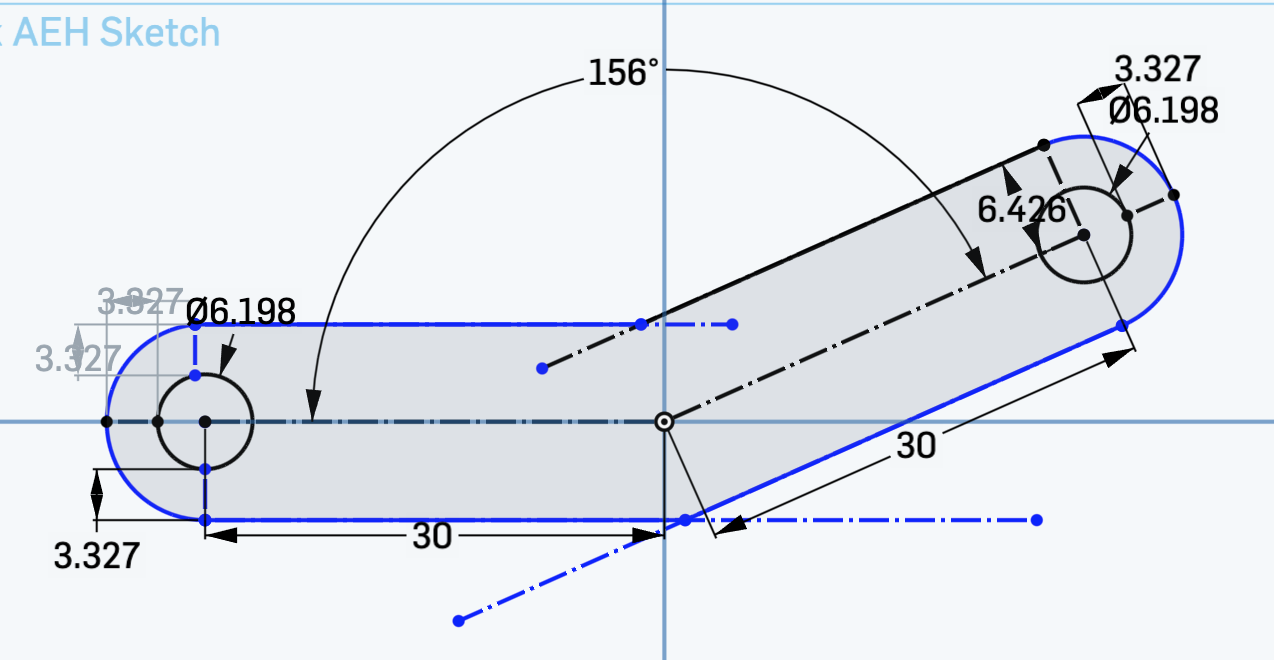
Okay, the tricky part was to select a "real" line that's colinear with (and shorter than) a construction line. This is where select other came in handy.
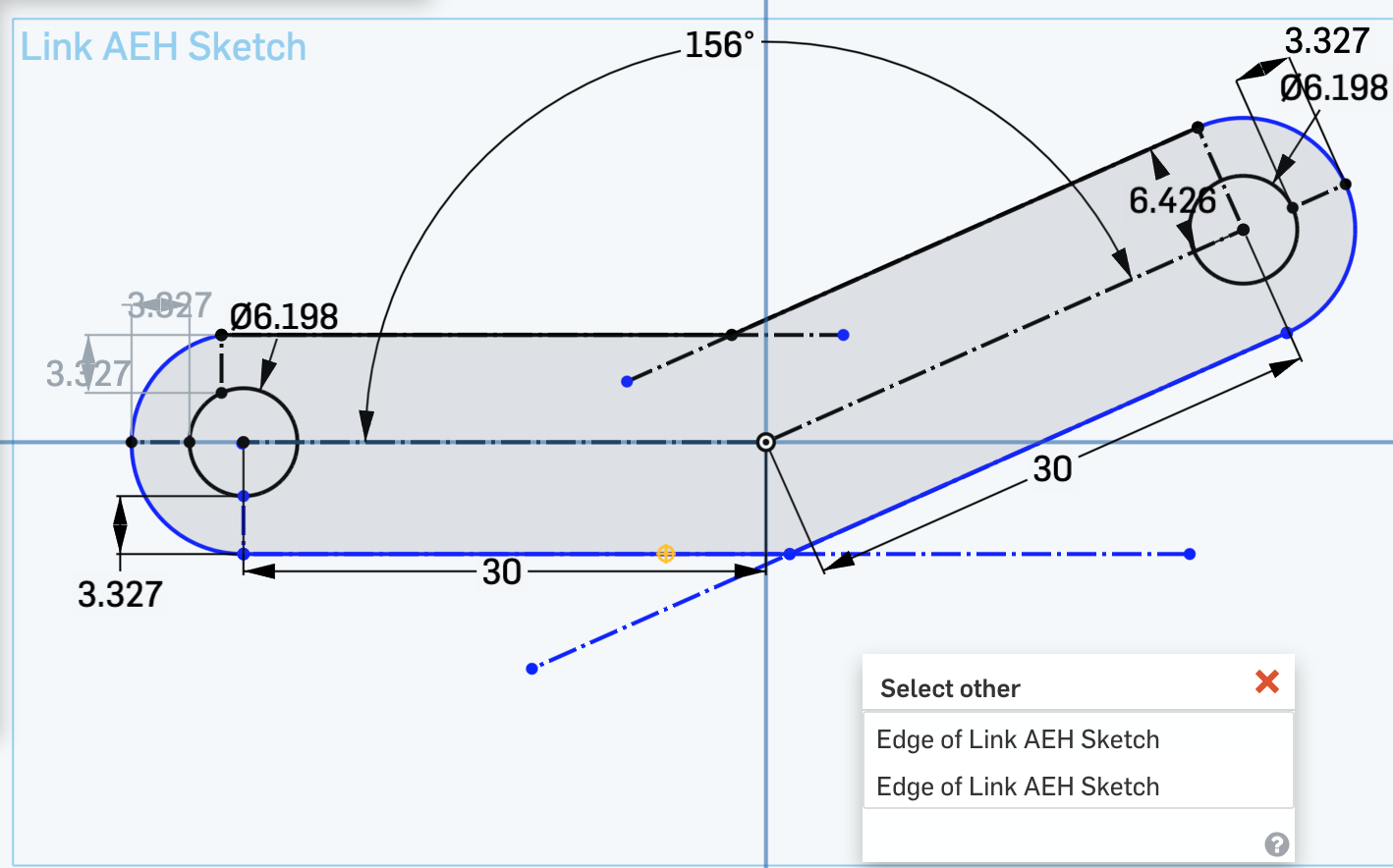
Nevermind, I had to reconstruct a bunch of stuff. Things are much better aligned, and even my construdtion lines are fully constrained.
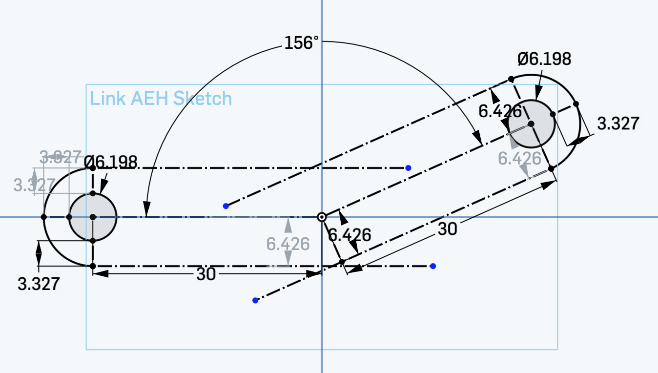
Yes! It worked!
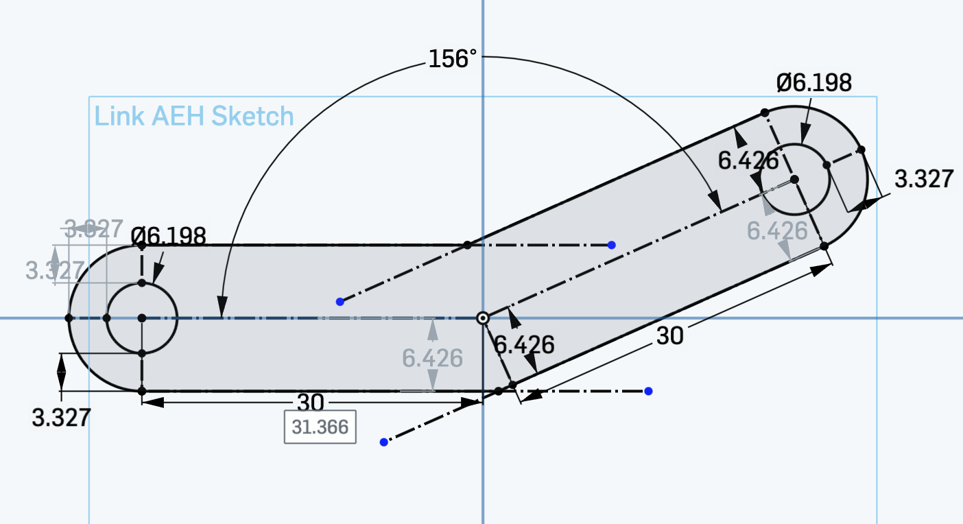
Re-extrude, remake the part, reposition in assembly. Can't wait to see how this turns out!

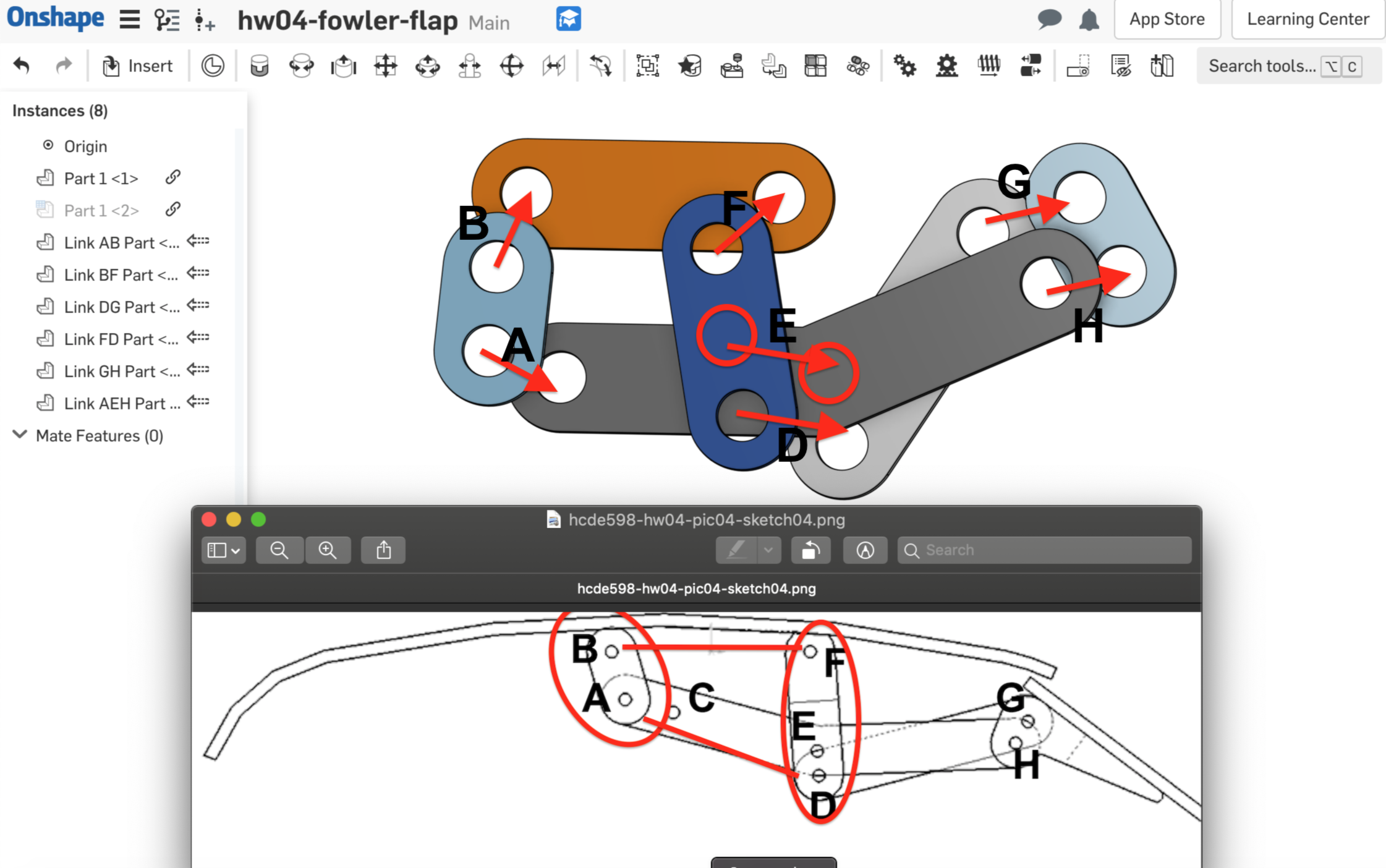
Basically I missed Hole E. I still don't beleve Hole C is necessary. I think it's there to attach a pushrod since this is for raido controlled model. I should also rescale some lengths.
| Link | Current Length | New Length |
|---|---|---|
| AB | 10 | 30 |
| GH | 10 | 30 |
| FED | 20 | 70 |
| DG | 30 | 90 |
| BF | 30 | 90 |
| AEH | 60 | 180 |
We've got our target lenghts from last night, so get on with it. Going from this ...

... to this! I was pleaed that bent-link AEH was as easy to scale as everything else; just re-scale each leg. I was concerned my dimensionins & constraints would have made it impossible to scale a leg without throwing the whole sketch into an unsolvable tizzy, but I somehow got it right this time.
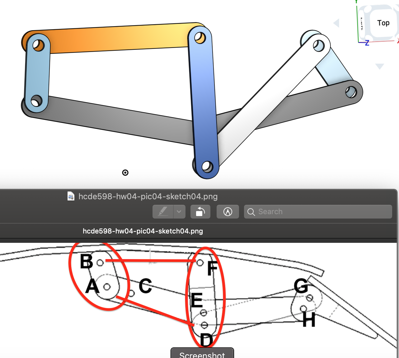
Y'know ... I'll bet there's an elegant way to make the length of one link proprotional to the rest, so I could just scale one measuremnt. I also think I'm not going to have time to find/learn it before this thing is due. Moving on ...
Eyballing it, Imma need to punch a hole right in the middle of AEH, and maybe two "hole widths" away from the bottom hole of FED
Link AEH turned out to be easy. I already had an intesection point at the "elbow," so I added a new crcle there, settng the diameter to match the other two.

For FED I added a new constrution line, dimensioned the length, then placed a circle there in the same manner as AEH.

The cool thing is, when I went back to the assembly, the holes where there! No "re-baking," rebuilding, or anything!
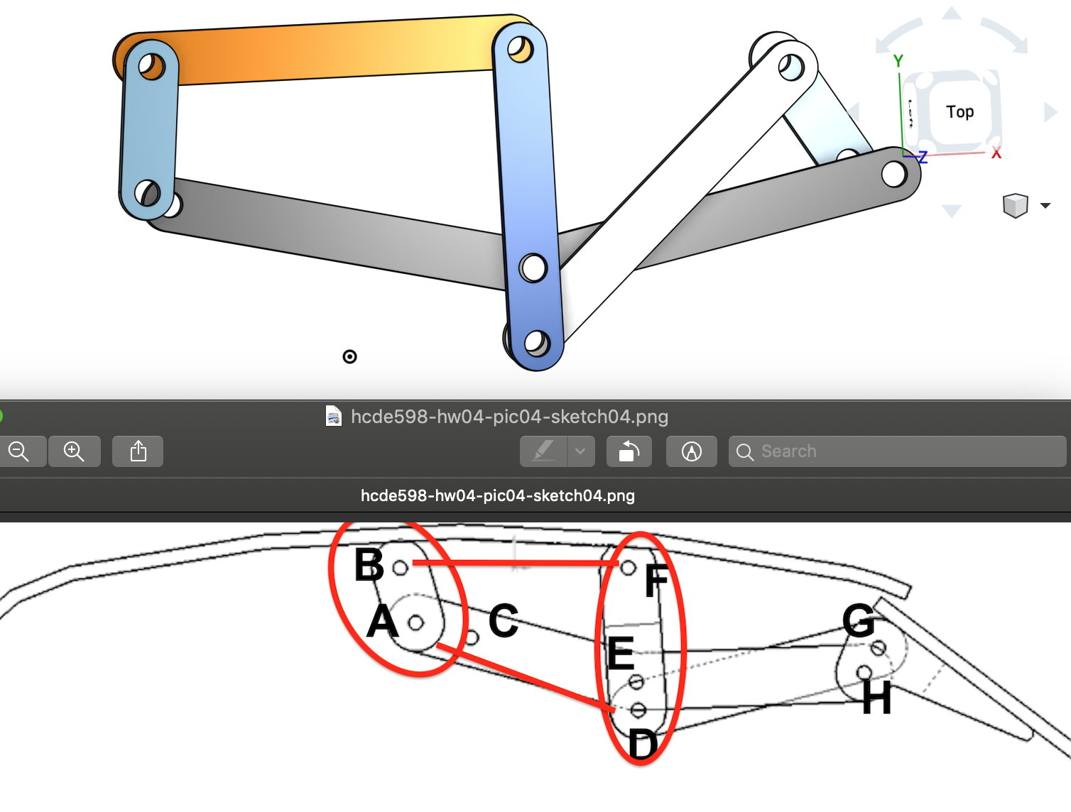
Okay, Imma 'bout ready to set some motion constraints and place some rivets. But first, Let's look at this thing from a different angle and sort how how many layers each rivet has to penetrate.
Looks like every joint is two layers -- never three (below.) It goes like this:
So everything's pretty normal, except GH is kinda wierd in the way it lies between AEH and DG.
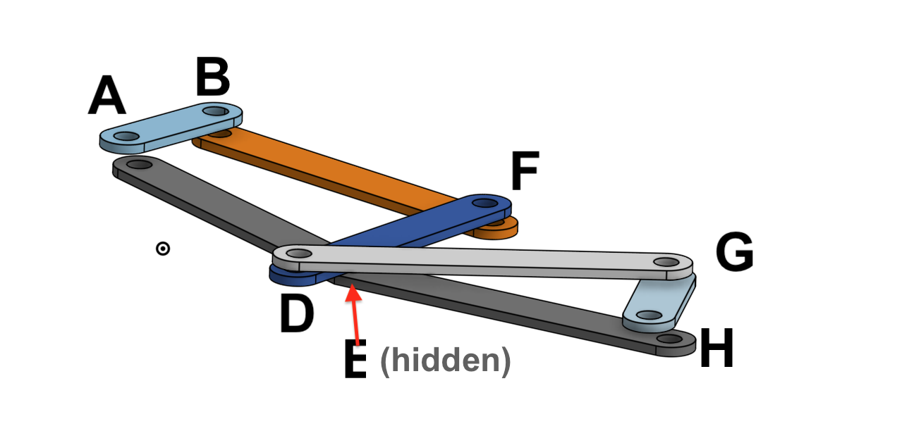
It took a lot of wierd twisty-turny orientations, but I was able to establish all the revoluate and fasterner mates.
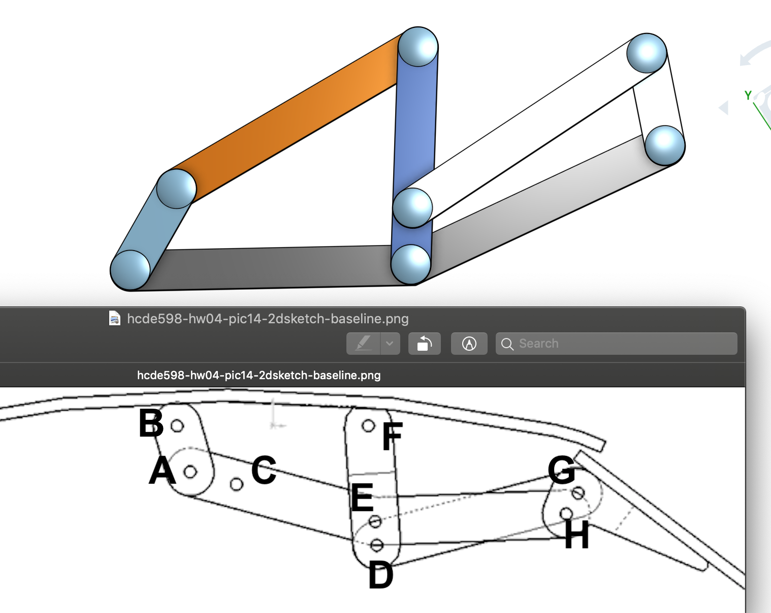
Can't quite get it to move though, I need to go back to Joshua's vidcap and figure out how he did that. Couldn't find it in the video, tried some googling, decided to use Fix to hold BF still while I move everything else. Things move, but Imma need to adjust some lengths.
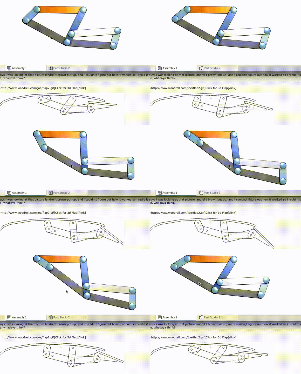
All right, let's pull up the "Pinned and Mated" figure, and add the pin labels.
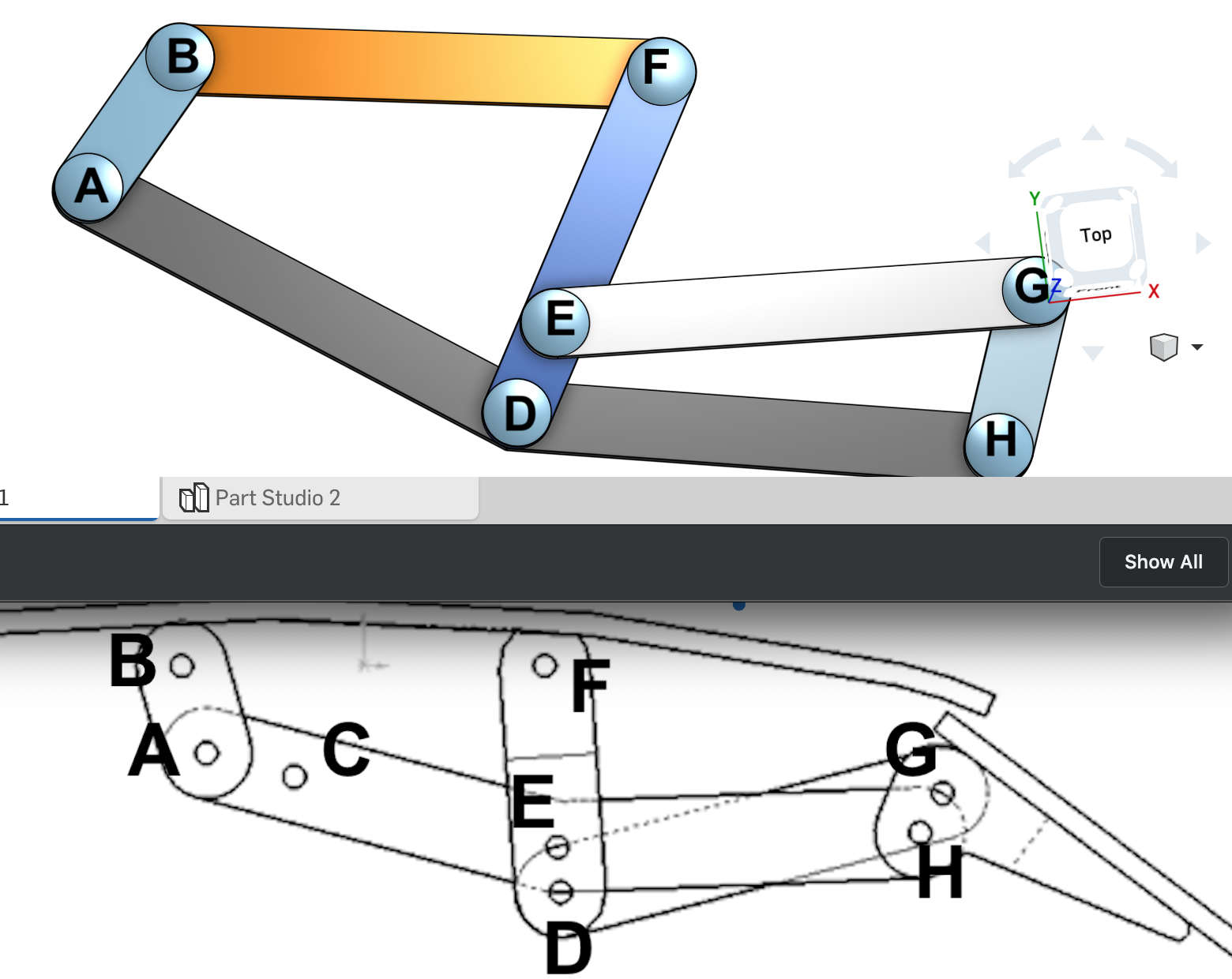
Okay, get closer to Ebola0001's flap likage, I'm going to need shrink AD by 20% or so to make AB point to the lower-right instead of lower left.
Hey wait a minute ... AEH and DG are pinned in the wrong place! Lemme fix that and try the motion again. Undo and redo some revolutes and fastners. Introduce rotation limits on AB. Add a nice animation and ...
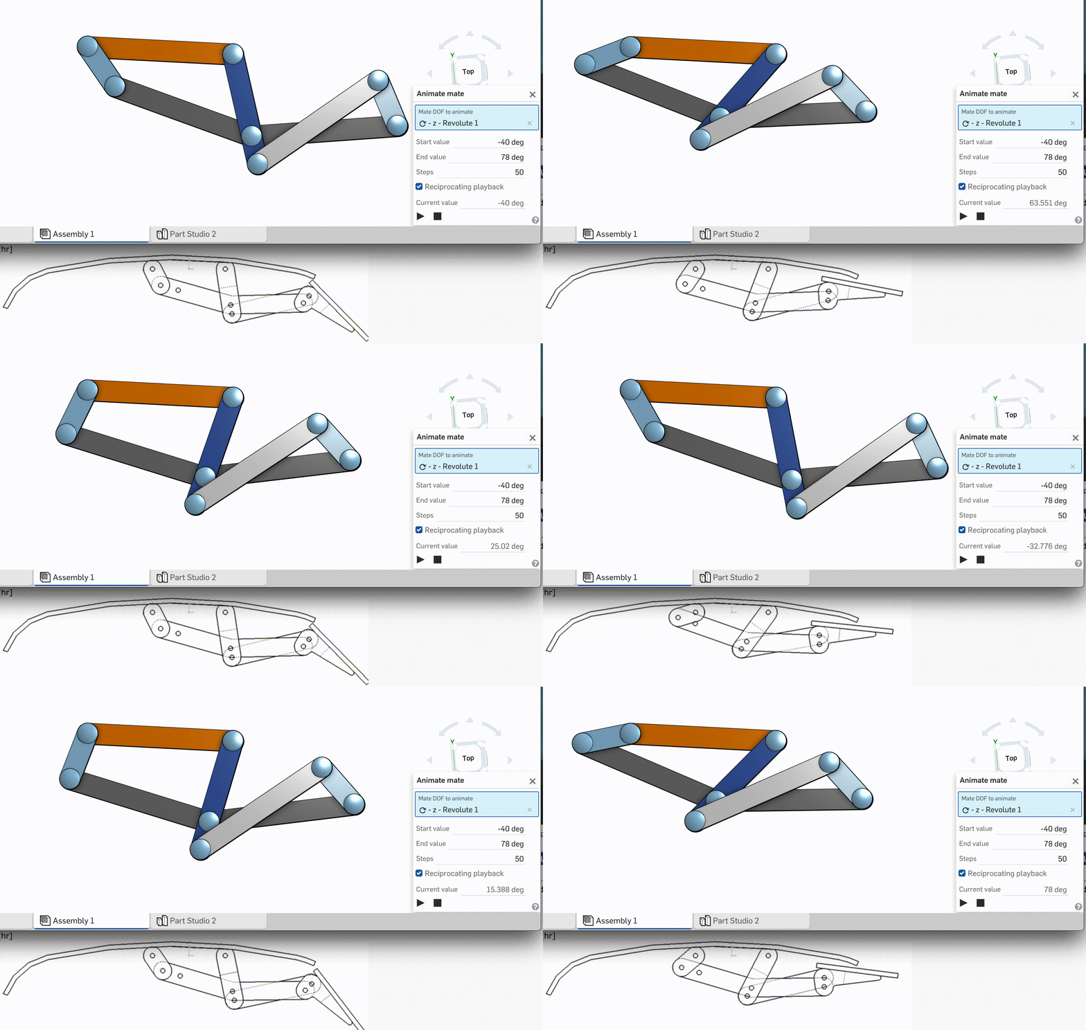
Imma go back to Ebola0001's gif and isolate the one frame where link GH is vertical. Here we go.
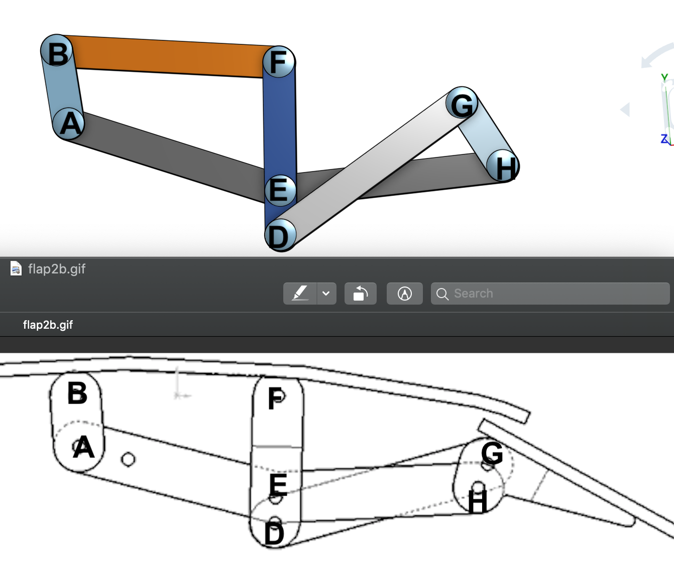
The main problem is GH. Link DG needs to be longer so GH points northeast instead of northwest. FED could be shorter but I'm scared that's going to throw a bunch of other stuff off. I'll just adjust DG for now.
Stay calm, stick to the plan and make DG longer. While we're at it, let's make GH look more like a flap.
Edit the Link GH sketch. Remove all the outer stuff, leave the two rivet holes behind. Add an arc on one side; two lines on the other.
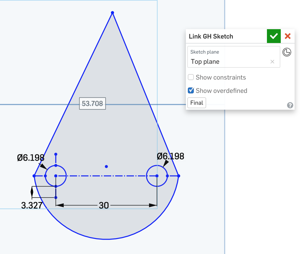
Add some dimensions to line things up.
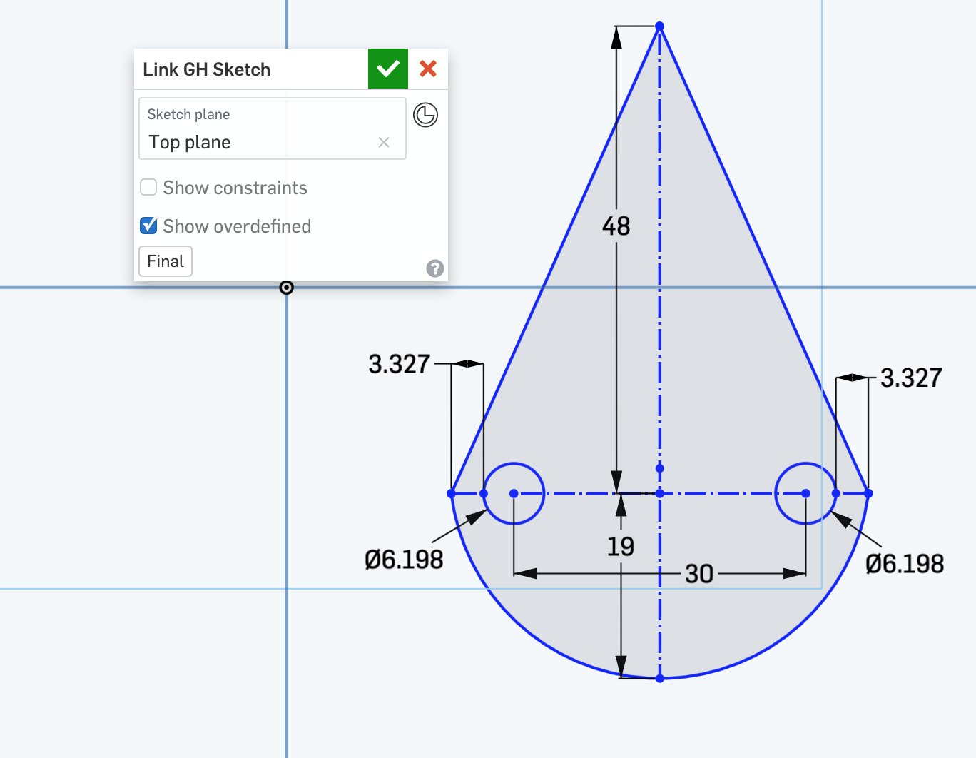
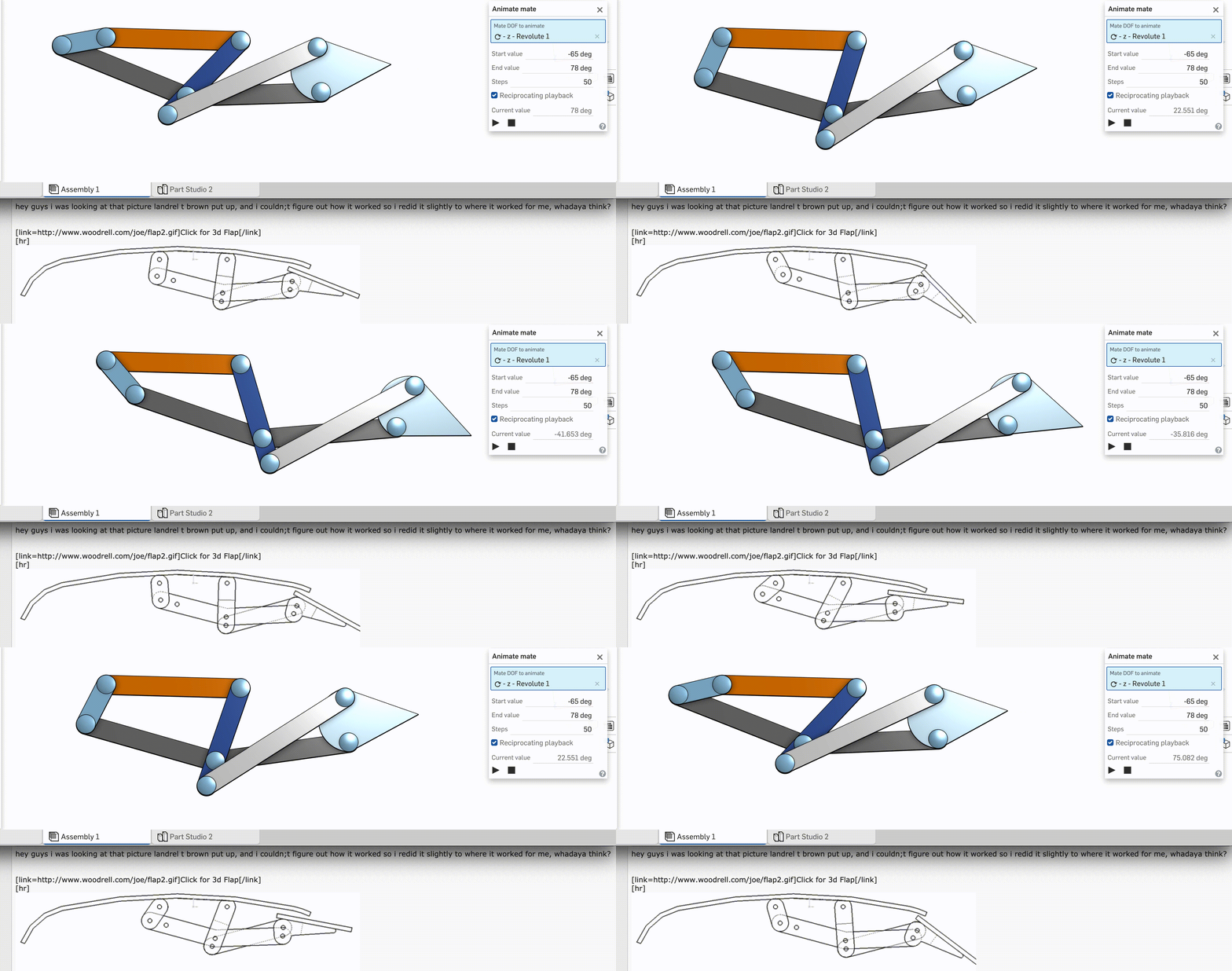
Try out the motion. Looks about right, but kinda hard to tell. Let's make the airfoil longer.
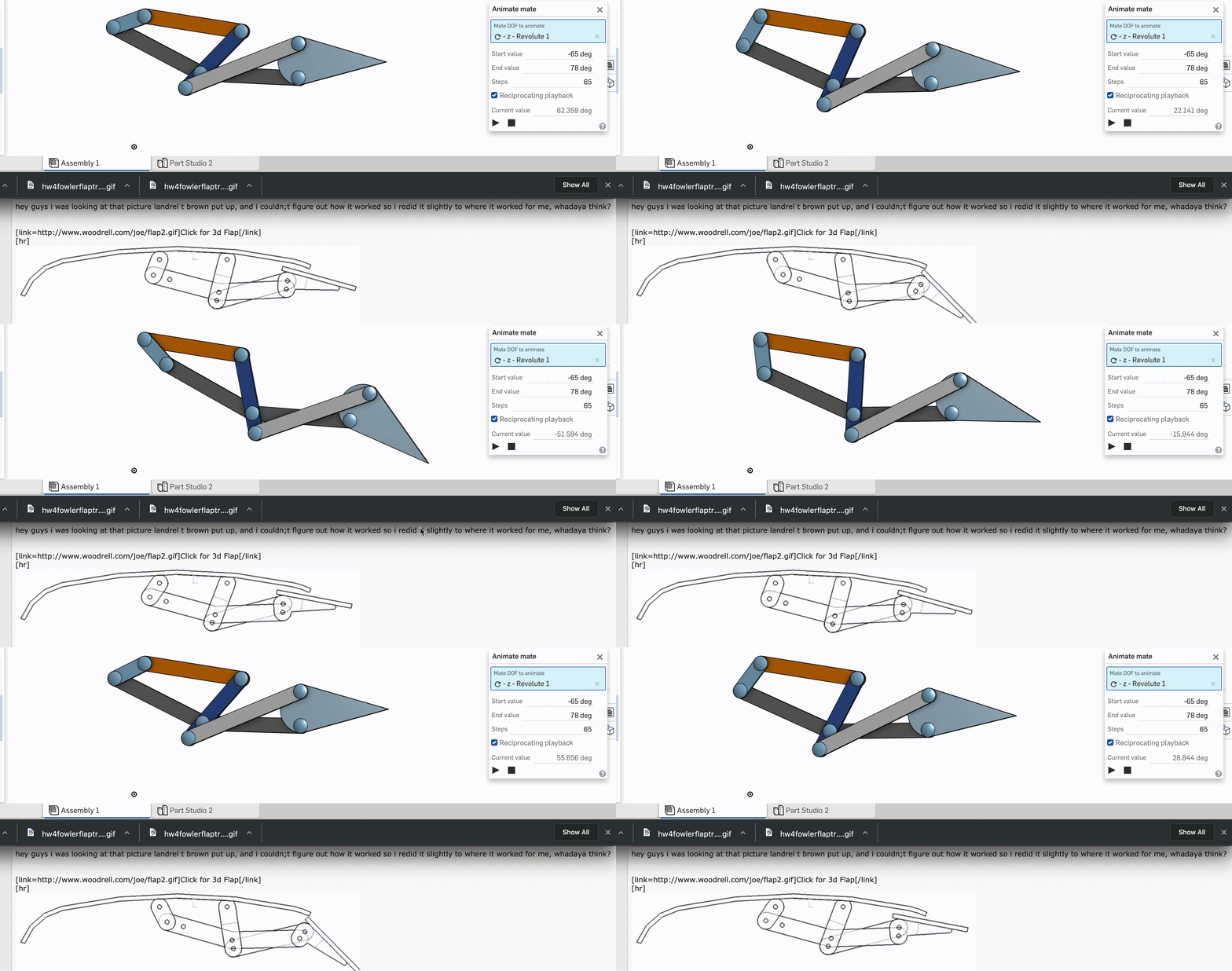
Bump up the 48 mm "taper length" to 80. Yeah I think I can live with this.
Wish I had time for legit NACA airfoils, but Imma print what I got now, maybe iterate later. Right, then; let's start with Joshua's kerf correction procedure ... took forever to figure this out. Eveentually needed help from Joshua direclty. Now I know to Make your Parts visible. I must've spent twenty minutes trying to Move Face on extrustions.
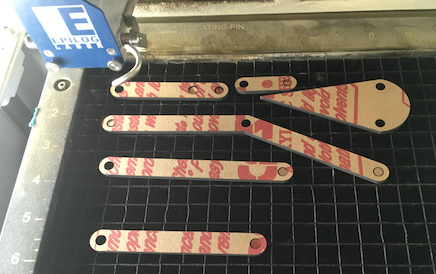
With that sorted, it was straightforward to export to DXF, and pull that into Adobe Illustrator. Just hand to set a 1:1 scale with units = Millimeters. Started with a test cut on cardboard to make sure IRL motion matched what OnShape was promising. Used regular cardboard settings from prior assingments.
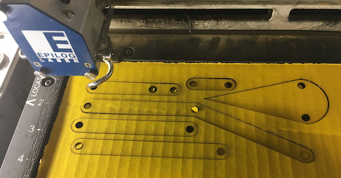
Right after lifting the parts out, I which I had labeled them. Thanks to OnShape, I could arrange them pretty quickly by size.
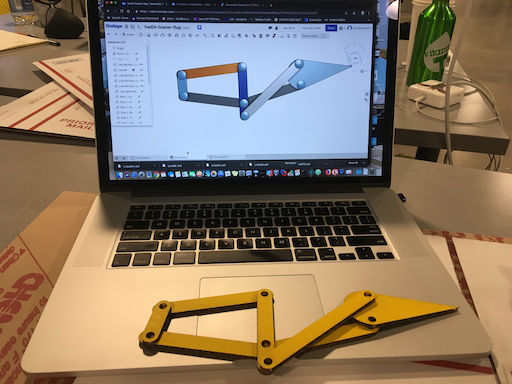
There was a bit of squish and crunch to get the fasteners throuh. The rougouness and pinchiness of the joints made movmement a little difficult, but it was still possilbe.
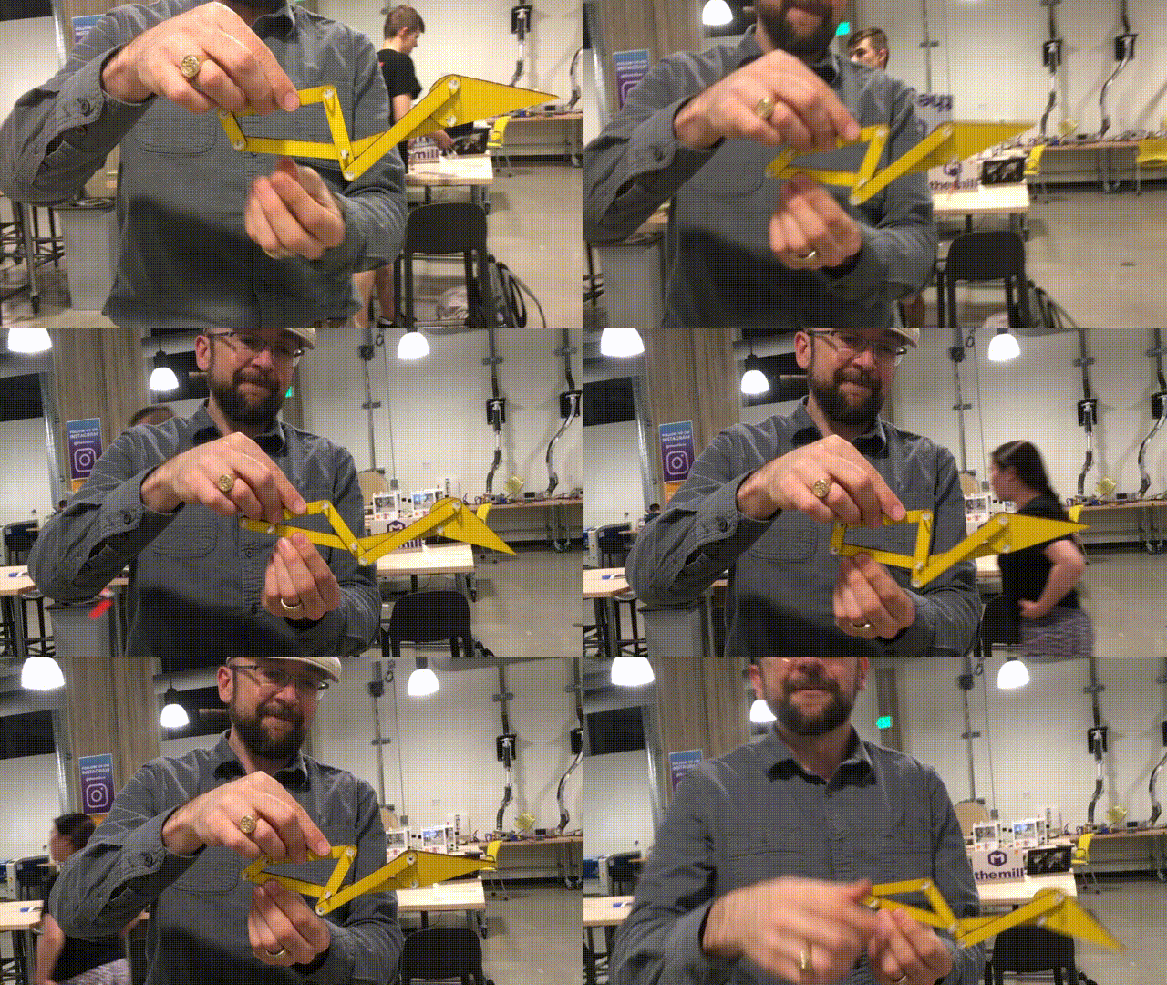
It's really disconcerting when everything's easy for a change. The only difference between cardboard and Acryllic was the speed and frequency setting.
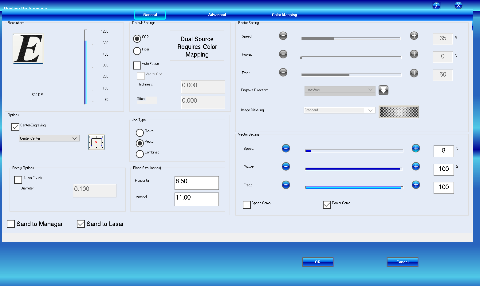
Also brief bits of "flame drama" as the laser burnt through the paper smudge and scratch protection, bugt the parts came out fine.
A scraper and some TLC got the paper off.
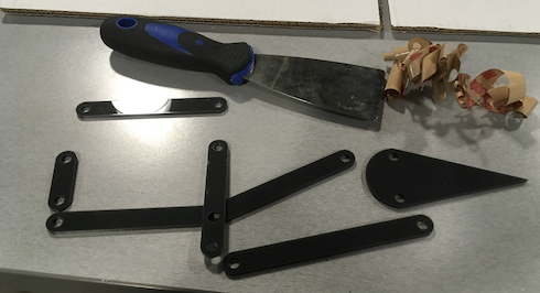
Fastners required a more oomph to get through the holes, but fit nicely once the were set.
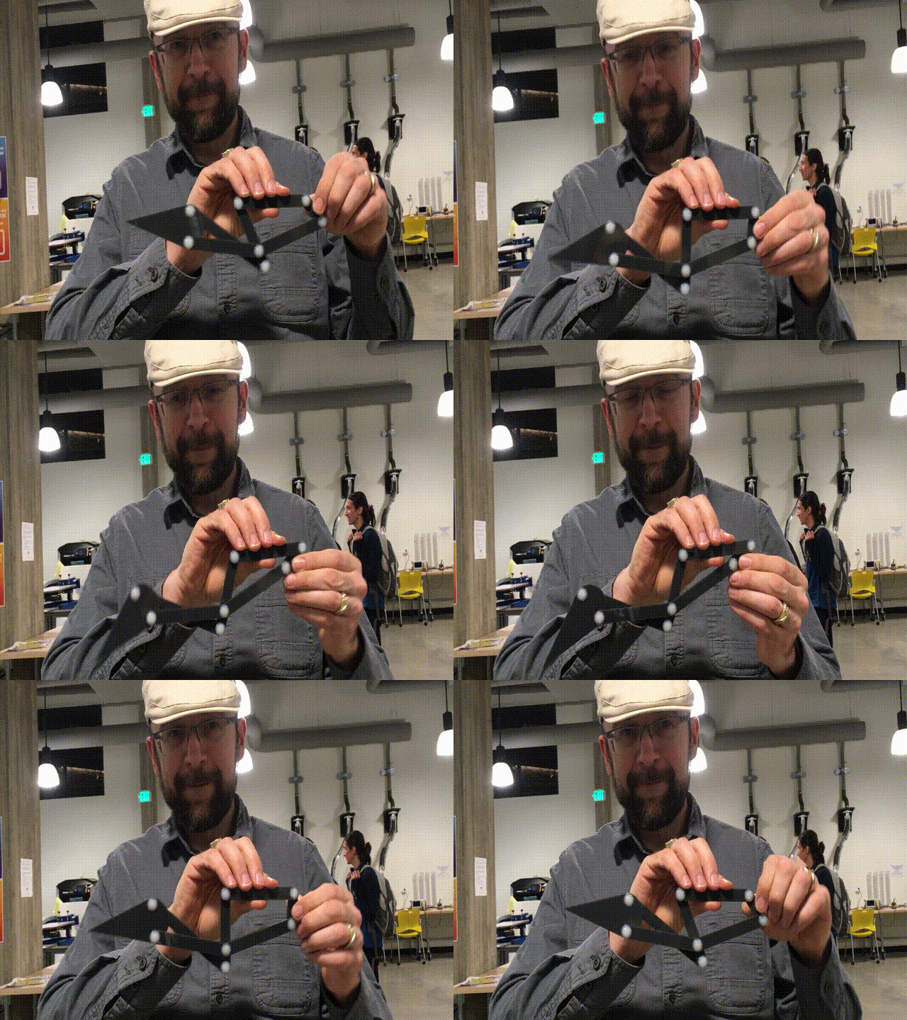
No time for fitting and simualtion on OnShape, but we can pull some foils direclty into Illustrator from prior homeworks, and scale to fit.


Couple more airfoils. This time make a hollow airfoil to hold the fowler mechanism. Before cutting, delete the linkage outline but keep those fastener holes.
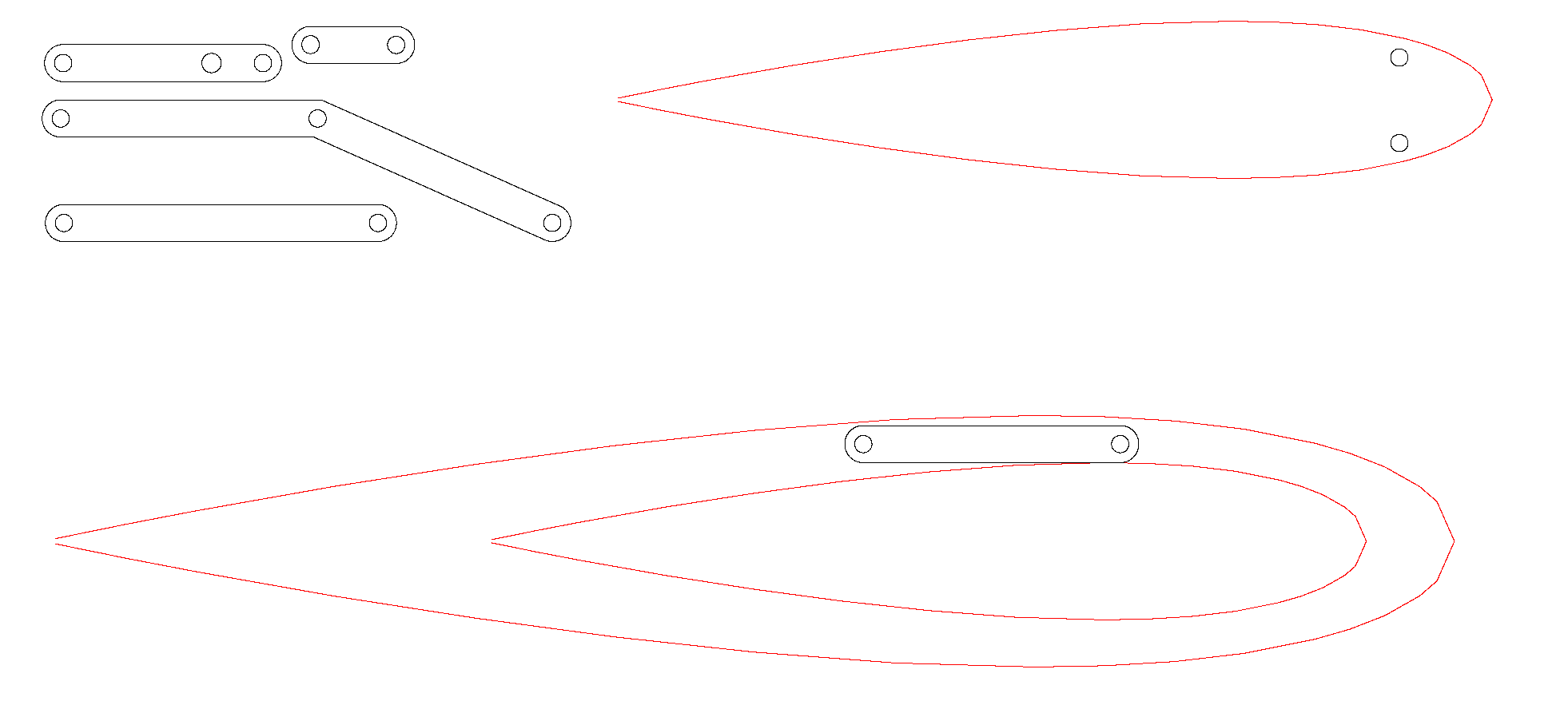
There was no fast easy way to line up the main airfoil, the fowler linkage, and the flap. All I could do is eyeball it, but I linke what I'm seeing.
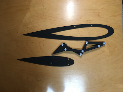
Pop off links BF and GH, snap in the airfoils and ...
