Leo's Assignment 5: Copper-Milled Wing!
Here is all the documentation for assignment 5!

Here is all the documentation for assignment 5!

The assignment says "box" but the FAQ's say any 3d object made of milled parts will do. So my good ol' wing with airfoils and spars should do just fine.
I've got my Grashopper scripts for generating airfoils and spars. They can be easily scaled down to fit on the FR-1. I'll need to be less cavalier about cut-outs, though -- none of this extra rectangle crap. I'll probably use OnShape for righteous airfoil cut outs, chamfers, and fillets.
This is where I start to have terrible complicated ideas that I abandon for something that's actually achievable. So "box" and "wing" aren't mutually exclusive. They exist in concept, and I believe a few small examples have flown.

But anyway, making one of these from the get-go is a terrible idea that would put my whole assignment at risk. So I'll get a conventional wing to exist first, then see if there's time left.
Dropping the Reality Distortion Field, an actual plan would be something like:
Took a day off yesterday, got some ideas on how to reuse/repurpose the in-class box demo. It's all about slots and notches. I can reuse the slots in my airfoils, and the notches in some between-foil spars.
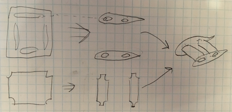
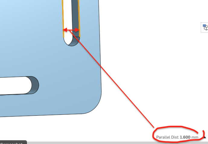
I'll probalby need to do the same "notch into notch" technique I used in my carboard wings. The key dimension here is slot width w (below). If I can assume that the in-class box demo will indeed product a snug-fitting box, then the widths of the slots should be the w I need.
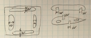
A little poking around with the OnShape file tells me w = 1.6mm
Okay, so to do this, Imma need to:
About that Worflow; time to view that in-class video capture.
My biggest worry is the airfoil. It's got a pointy trailind edge, so I'm worried Bantam might kick up a fuss with the tool paths. Time to fail fast and get a simple foil into Bantam ASAP.
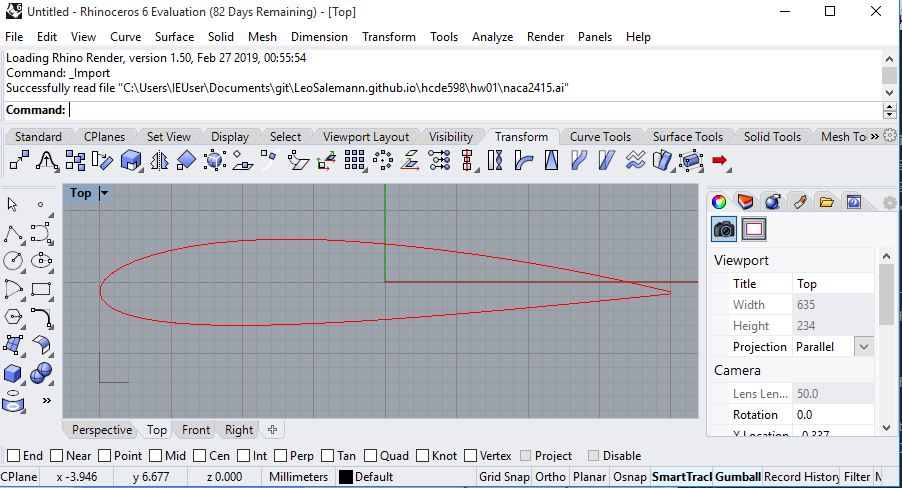
Rummage through previous homeworks, find a simple airfoil, pull into OnShape. Turns out 3dm's import just fine. Here's one from Homwork 3, just need to whack out that rectangle.
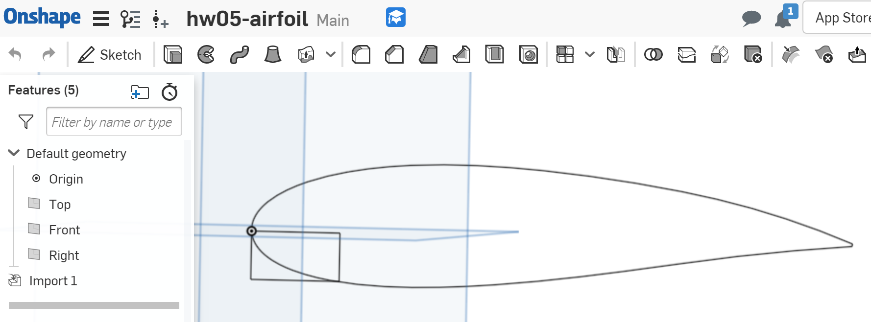
Extrude the airfoil by 1.87mm, matching my FR1's thickness ... not working. OnShape doesn't seem to acknowledge the imported 3DM as a legit curve.
Try Rhino. Can't really find a clean airfoil with no notches, so go back to Dr. Gareth Paterson's NACA series 4 airfoil Generator (Grashopper Definition) from Homework 3. Fiddle with the inputs again until I get something thick, no unusual curves, but still a recognizeable airfoil shape.
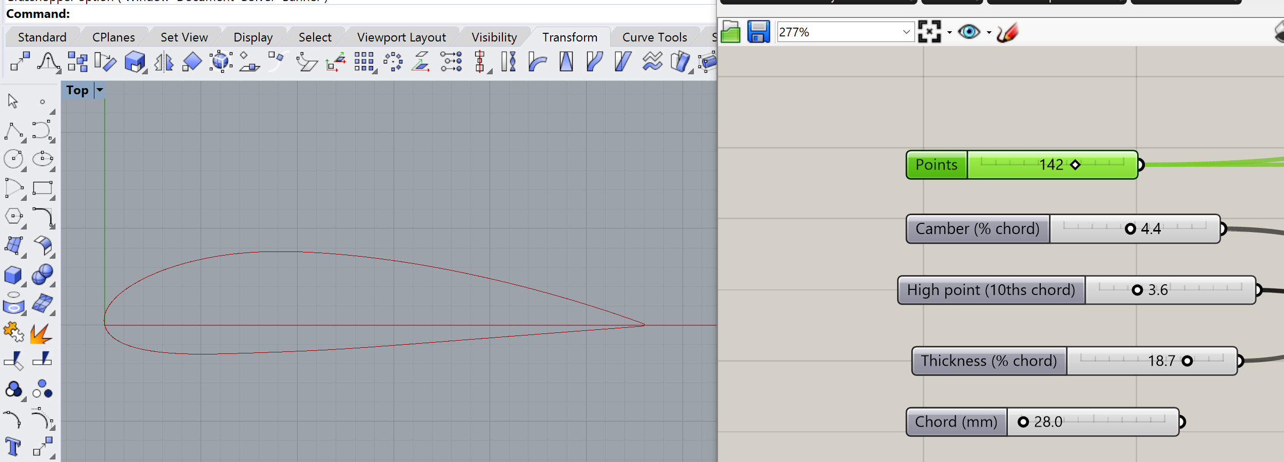
Now there's a couple things to try. I could go direct to DXF from Rhino, pull into KiCad and Bantam. That'll let me validate tool paths the fastest. Later, I'll try a Rhino -> OnShape -> KiCAD->Bantam workflow so I can do all the part-fitting and fillet-cutting in OnShape.
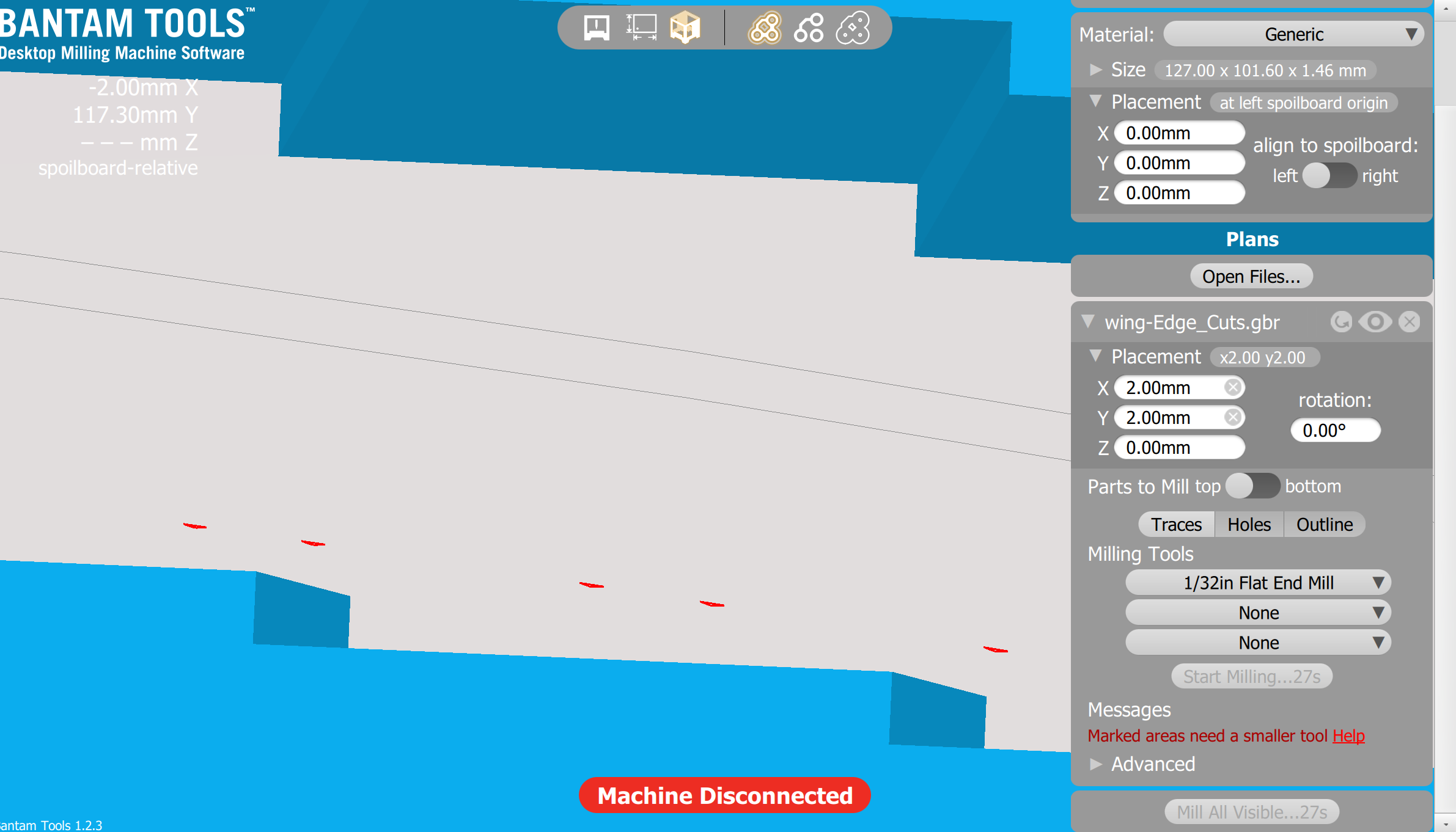
Interesting. It says Marked Areas need a smaller tool but it looks like it will cut just fine (or close enough, anyway).
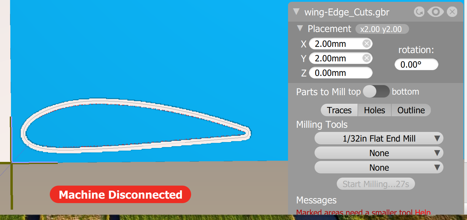
Zooming in, it looks like may airfoil picked up some "jaggies" (aliasing) during the imports and exports.
Go back to KiCAD ... looks pretty smooth there. Try plotting from KiCAD again.
Going back to Rhino, the airfoil looks smooth. Retry the export, there's more than one scheme avaialble.
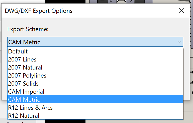
Try CAM Metric, pull it through KiCAD then Bantam. No more warnings.
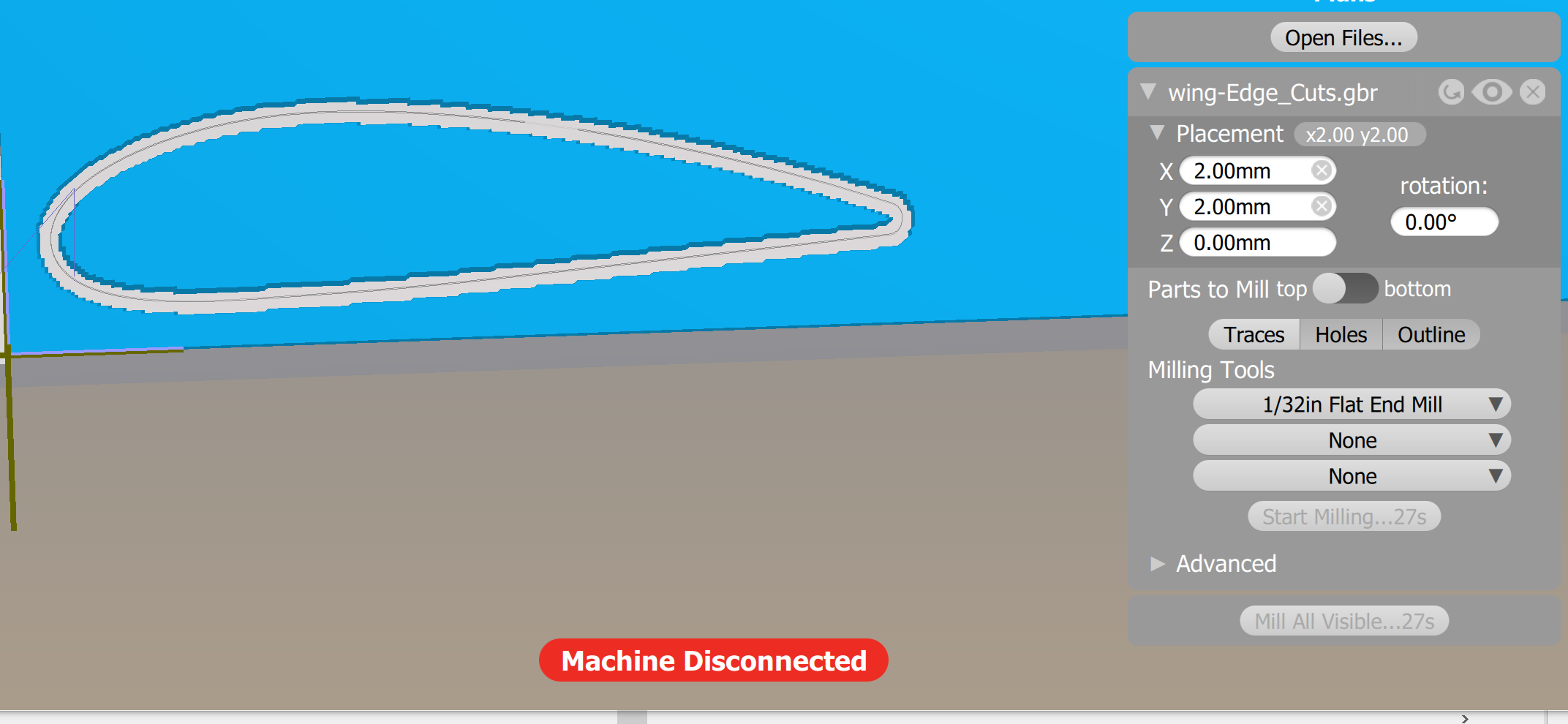
Okay, so I'm feeling confident I can get Bantam to cut me an airfoil. Rather than cutting a solid foil that can't be used, I wanna print the minimal number of parts that validate airofoil shape as well as assembling foils and spars. Two foils, two spars, Joshua-Style joinery will will prove out all I'm looking to prove, and could be a MVA (Minimally Viable Assingment) in a pinch.

Right then, off to OnShape!
Let's grab that CAM Metric dxf that worked so well in Bantam, and see if I can make an OnShape Part out of it. Interesting, it came in red on black

A little googling tells me I'll probably have better luck importing the Rhino 3DM file. Having the same trouble getting from curve to extrusion though. Lemme try extruding in Rhino.
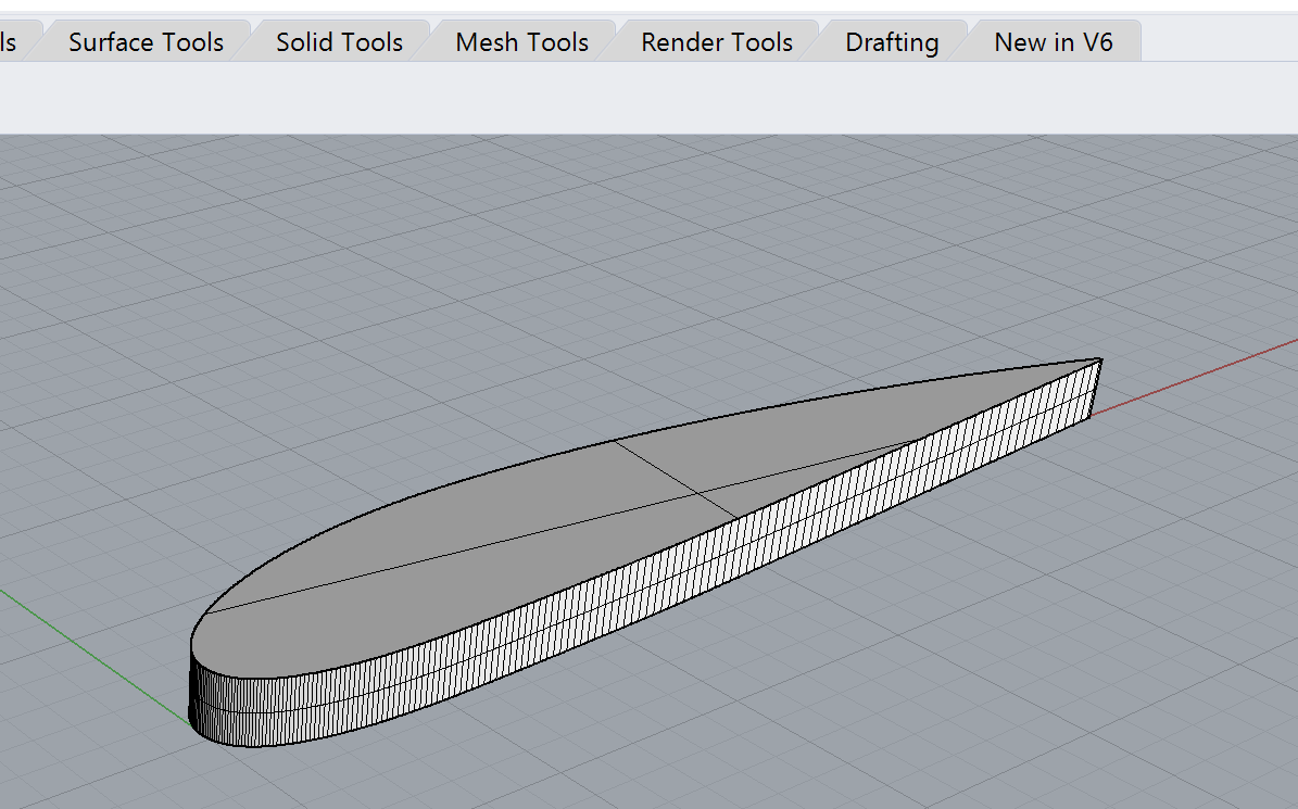
This is encouraging. Onshape recognizes it as a Part. Now let's see if I can get the airfoil part and Joshua's box parts to play nice in the same assembly. Yeah.... Imma need to separate some aprts.
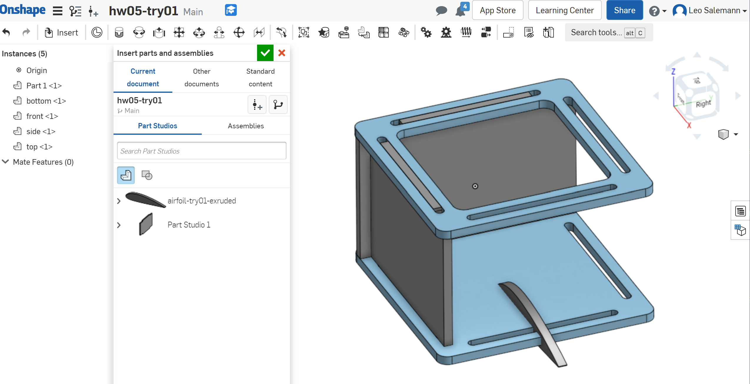
Okay, after fumbling around with the mouseology, I managed to grab the sketch of Joshua's box top and paste into the part studio of my airfoil. Now I can (hopefuly) Grab one of his slots, shorten it, and cut a hole or two into my airfoil. I might-just wanna larger airofoil, actually.
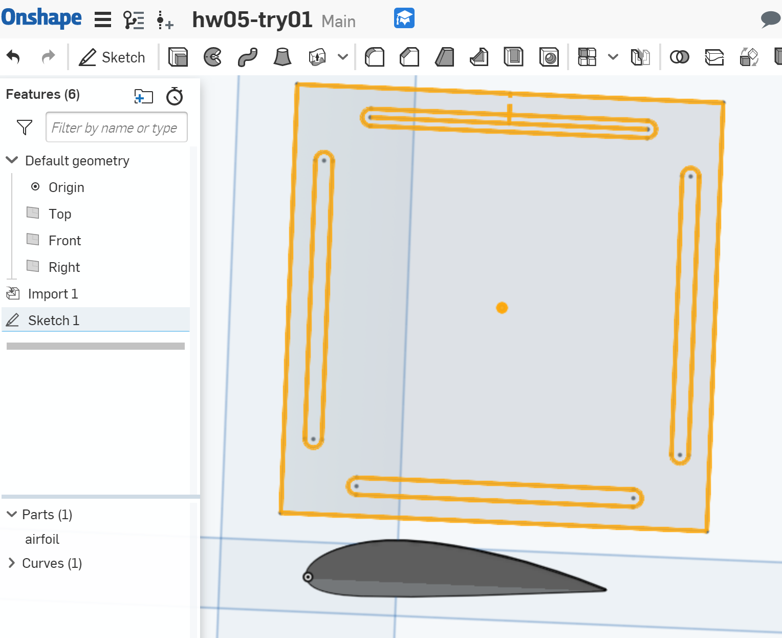
Looks like I need to re-dimension after the copy/paste.

Okay, now if I can shrink the lenth from 26mm to 2 or 3, copy, paste, and ...

I dunno ... it's not really working because the airfoil is a part, a curve, but not a sketch. I'mma put the holes in with Rhino ... nah, I miss my OnShape dimensioneering.
Hey, wait ... maybe I can import dxf into a sketch after all. Create a new sketch, import form DXF, copy/paste shape elements from Joshua's box, extrude by 1.6mm, and ...
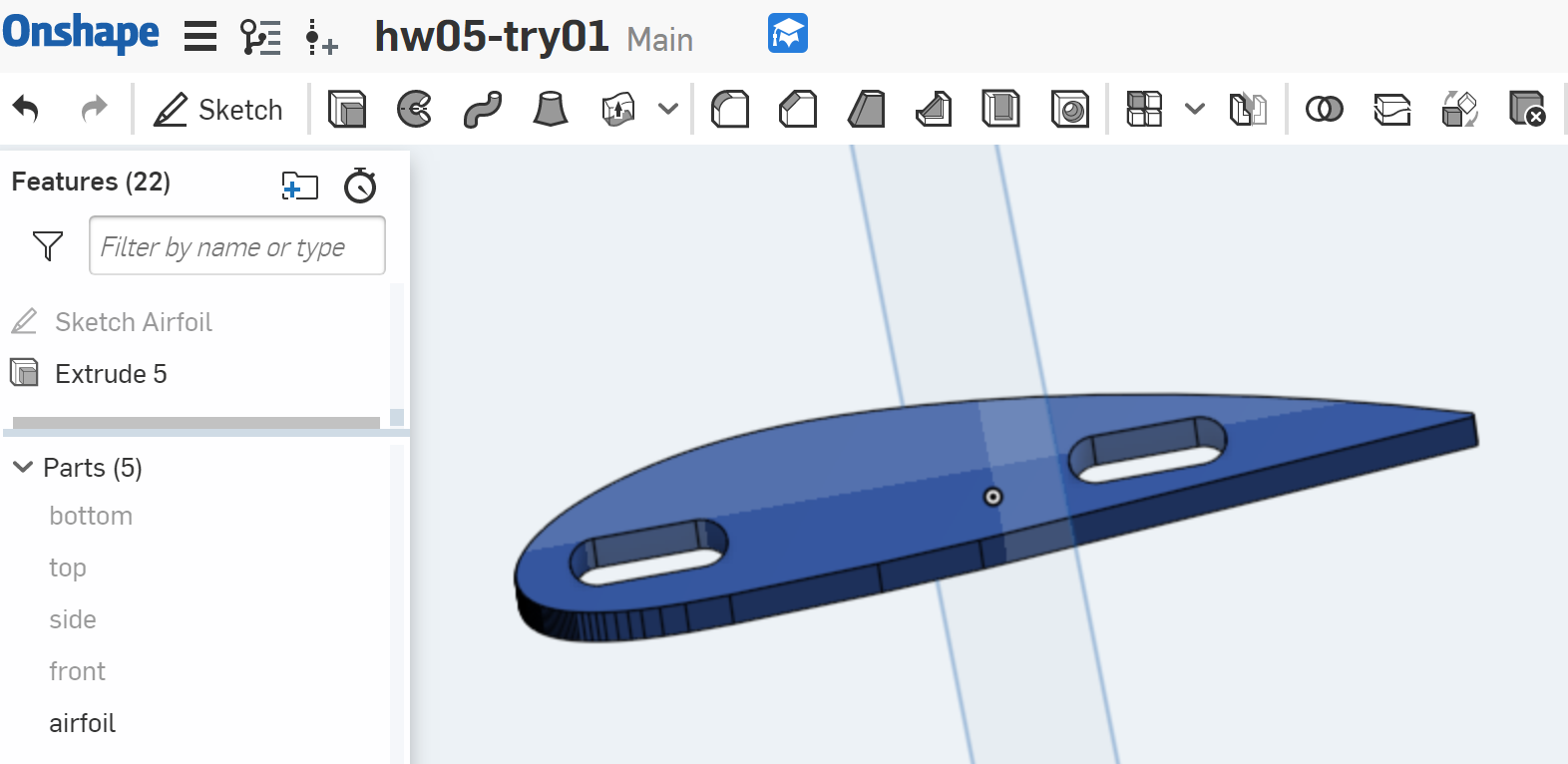
This should be as easy as taking Joshua's box-side and shrinking a dimension or two. But first, some measurements.

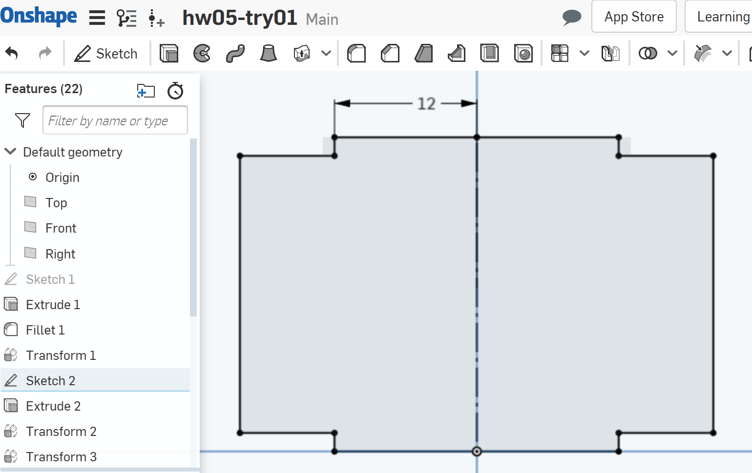
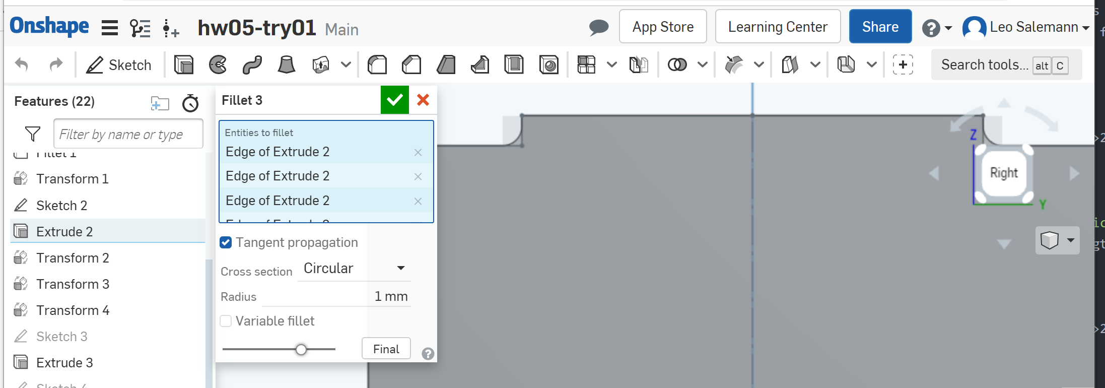
The key thing here, is that the slot is 2 mm longer than the notch. So we probably wanna 4 mm slot with a 2mm notch. Then, we gotta ...
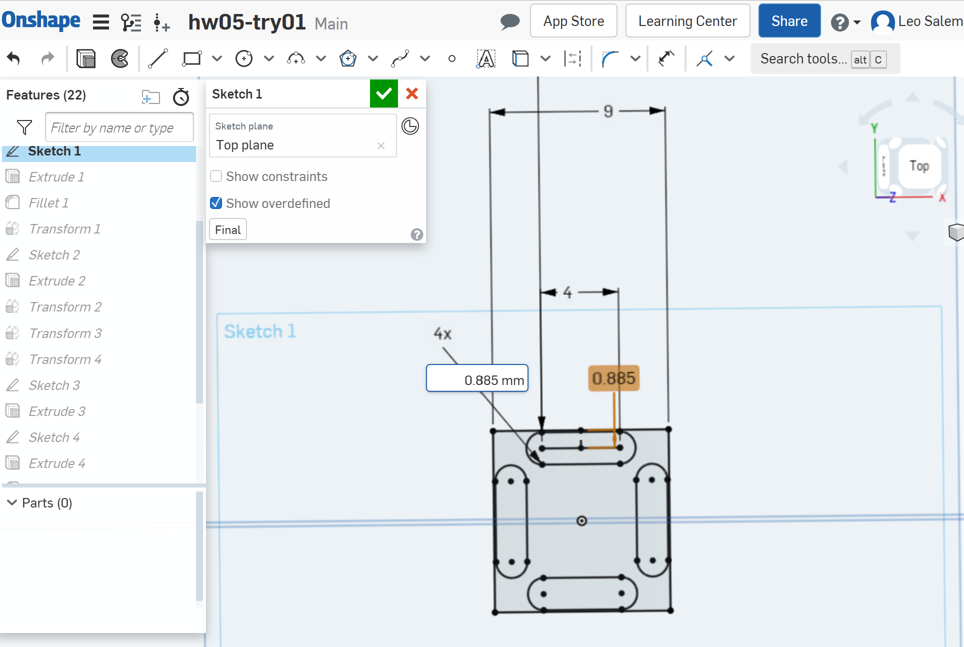
Turns out all the sketches and dimensions in Joshua's box are inter-realted to each other. First, shrink his slot lenghts on his Sketch 1down to 4mm.

Next, Fiddle with Sketch1 side lenth and slot-to-edge distance to make the smallest box possible. Baslically side length can go down to 9mm and slot-to-edge can go down to 1.57/2 + 0.1 before anything breaks too badly.
Moving on to box sides (Sketch2). Shrink the noth half-length from 12 mm down to 2. The rest of the side got "skinny" after shrinking Sketch1.

Now it's a matter of parts-wrangling in assembly mode. Forget the pin and slot mating, forget the fancy-shmancy part-level transforms. Imma just grab, move, rotate until it looks about right.
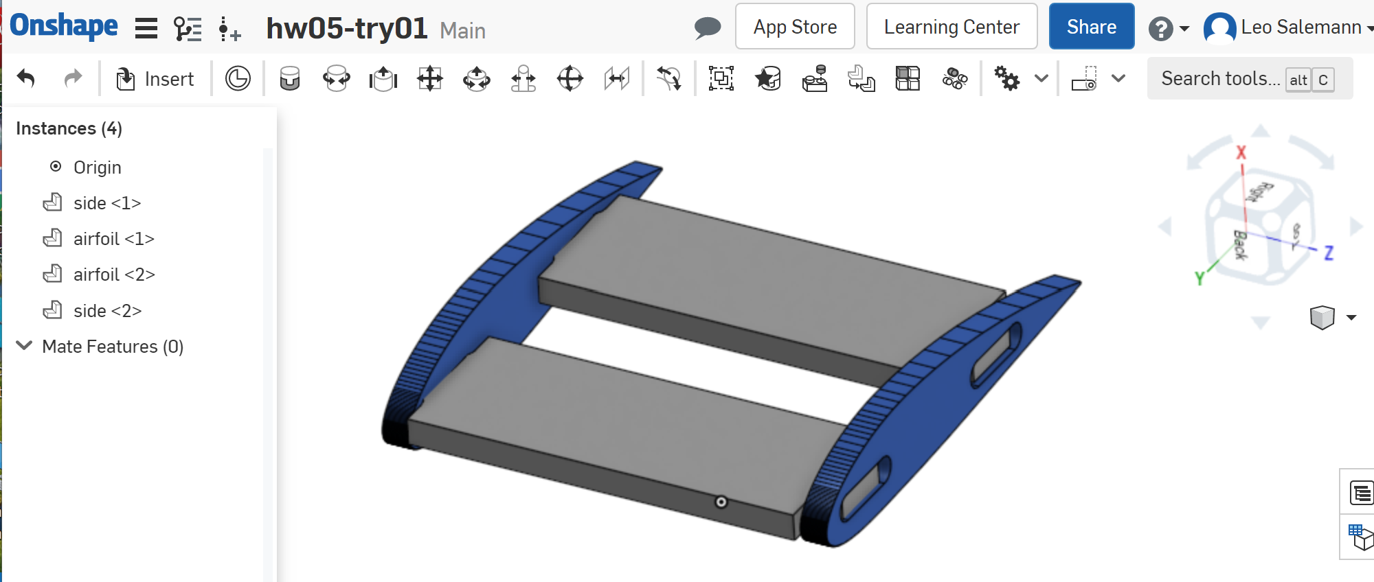
Grab the spar, grap the foil, export eac to its own DXF. Load those into KiCAD
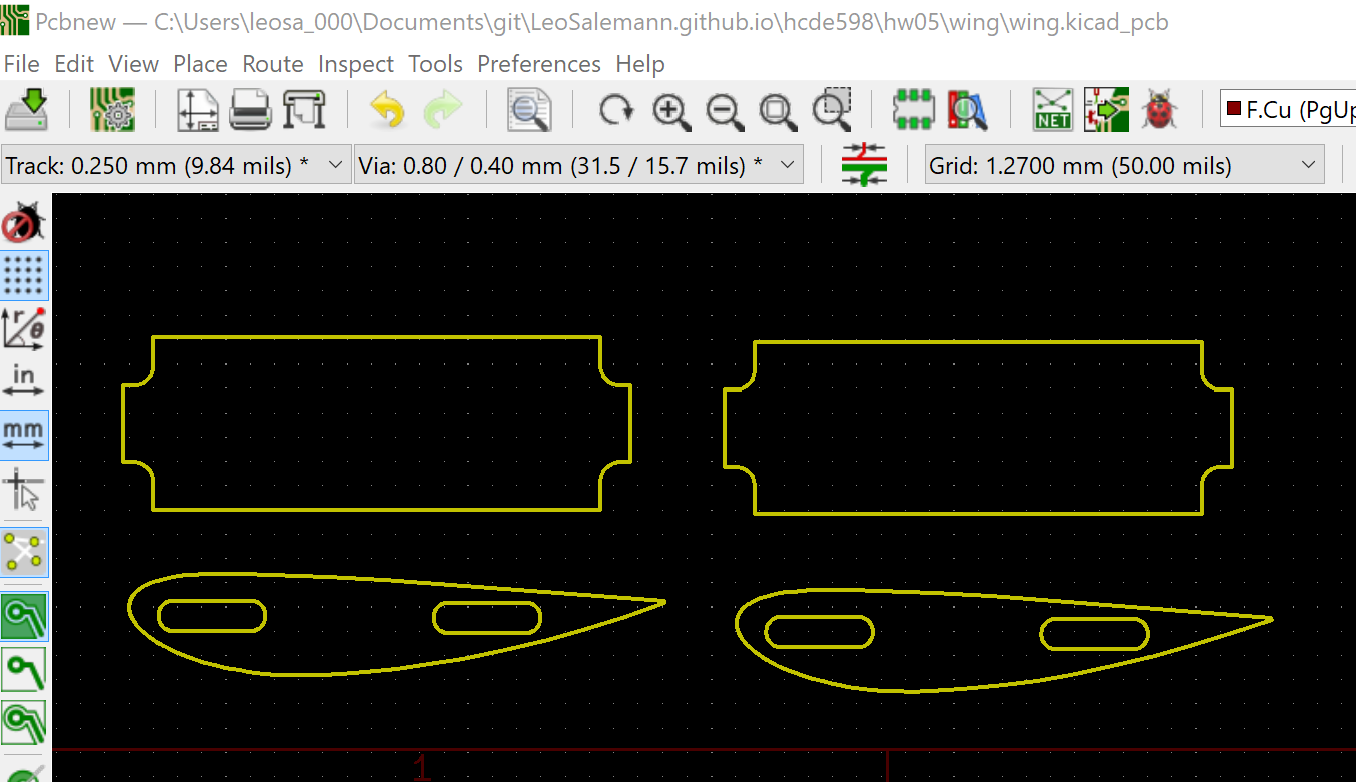
Hmm .. those aft spar slots (near the pointy end of the airfoils) don't look like they're going to leave much material behind, but let's take them into Bantam to see what it says.
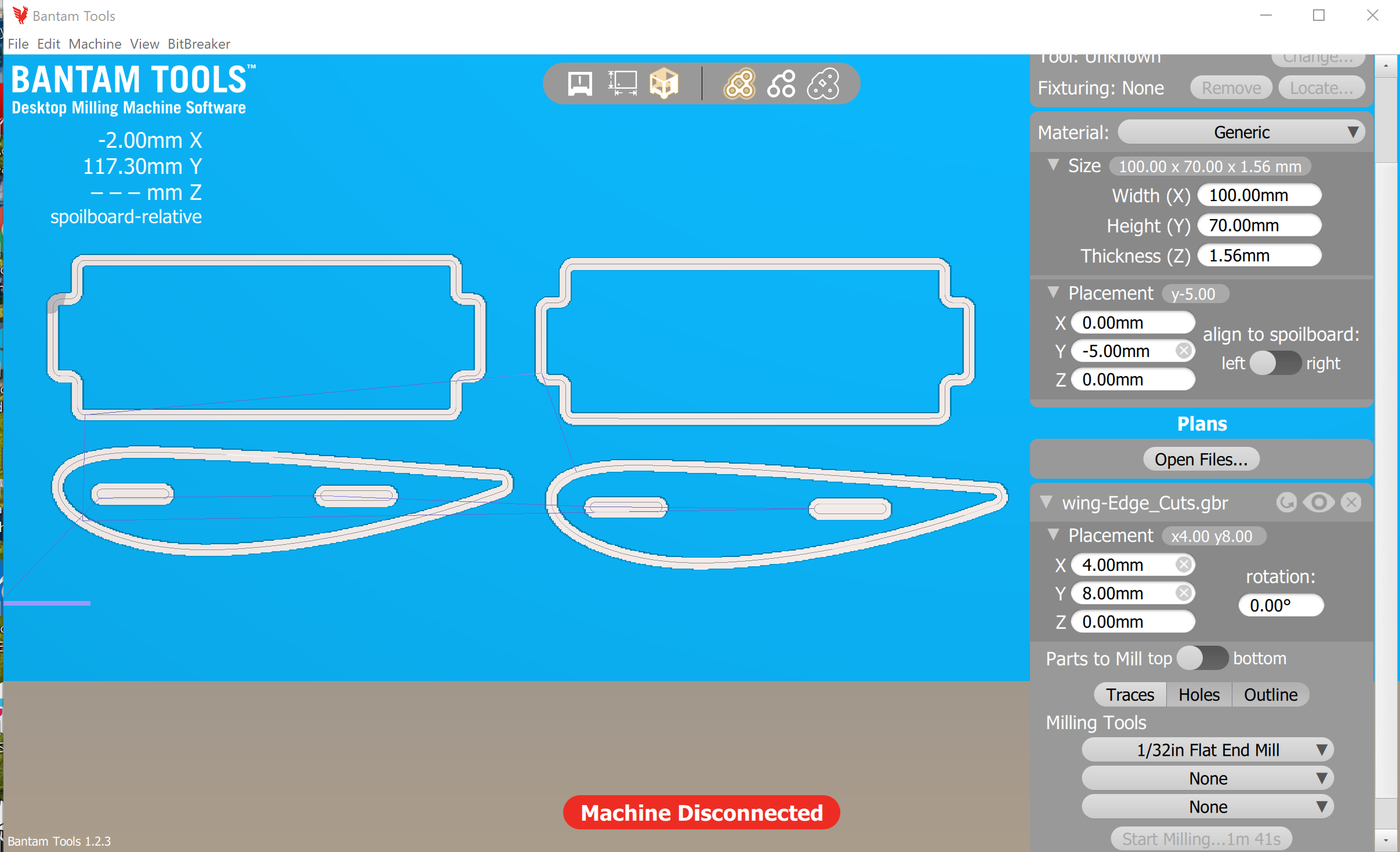
Huh, no complaints.
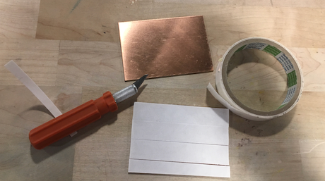
These are gonna be small parts with thin bands of material, so imma lay the tape across the whole board.
Caliper says my sandwich is 3.60 mm thinck, while one board is 1.52 mm, so my z-offset needs to be 2.08
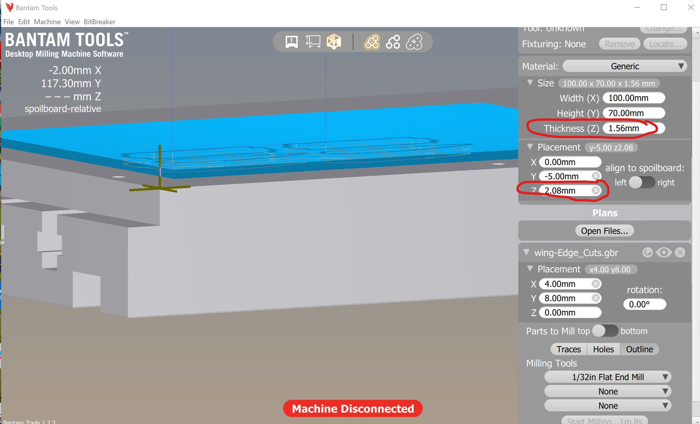
Dammit! No slots in my airfoils!
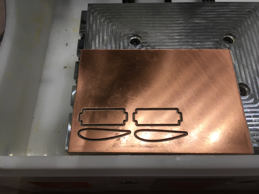
Sure enough, I somehow loaded the wrong airfoil Bantam.
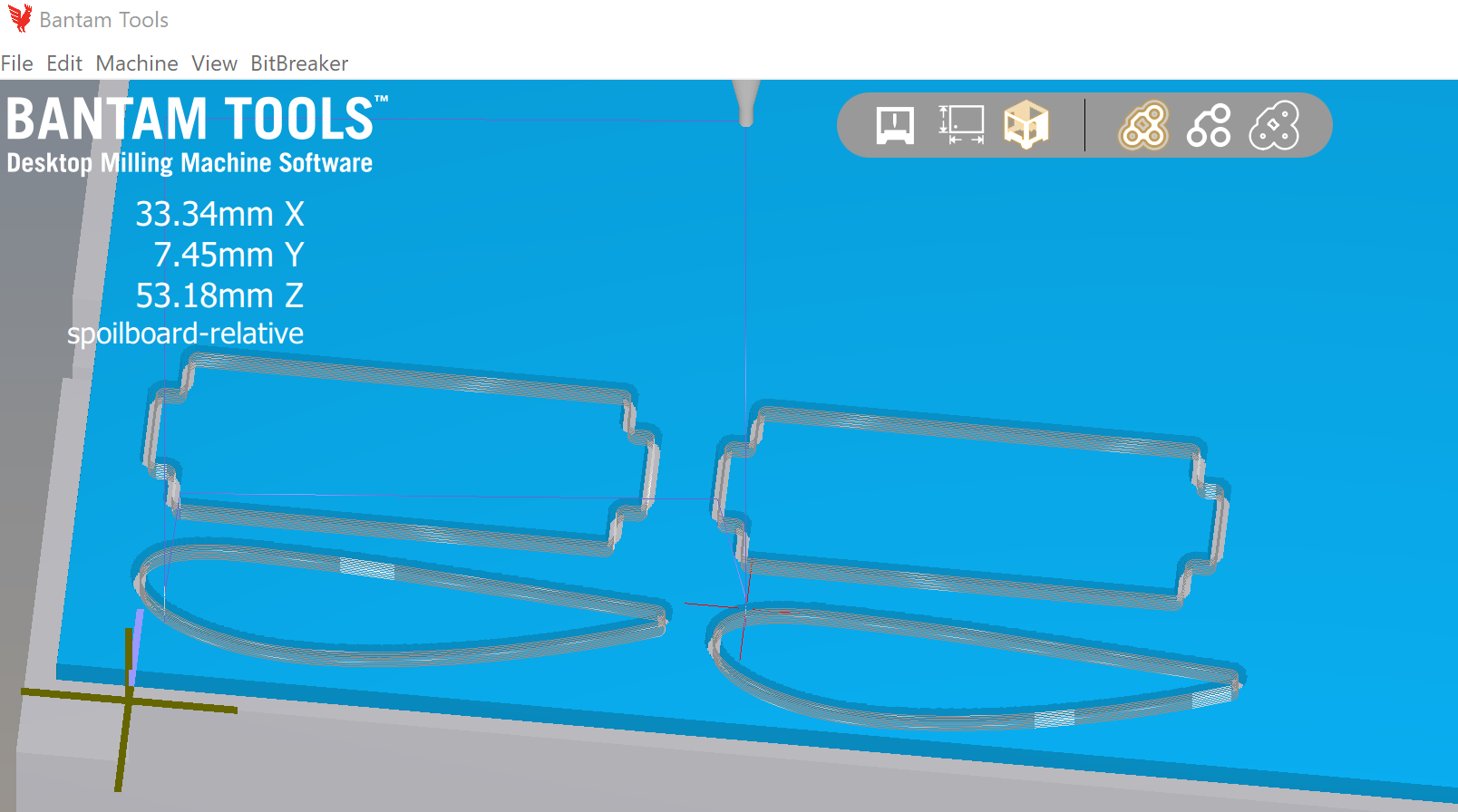
Wait a sec, I can see the hols in KiCAD just fine
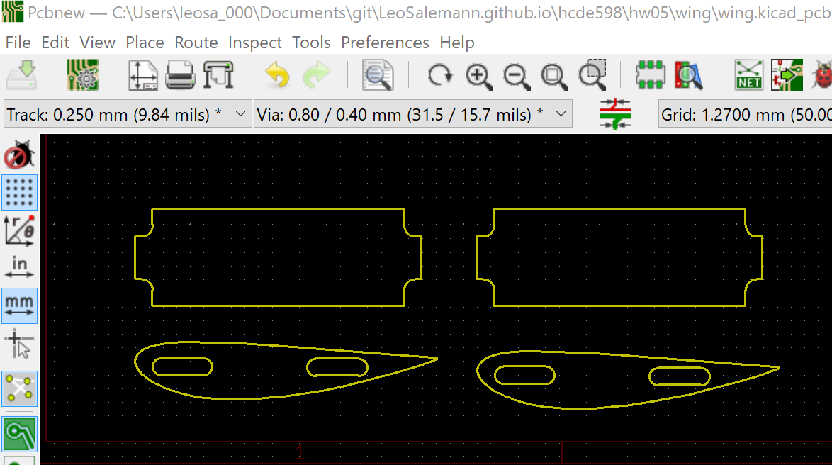
Actualy, I think I had holes turned off.
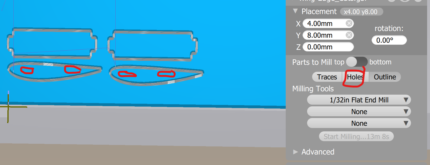
Took another day off, I'm such a hedonist. So it almost worked last time. I got airfoils, spars, but no slots for the spars to fit into. After some thrashing around, i figured out I simply had left Holes turned off.
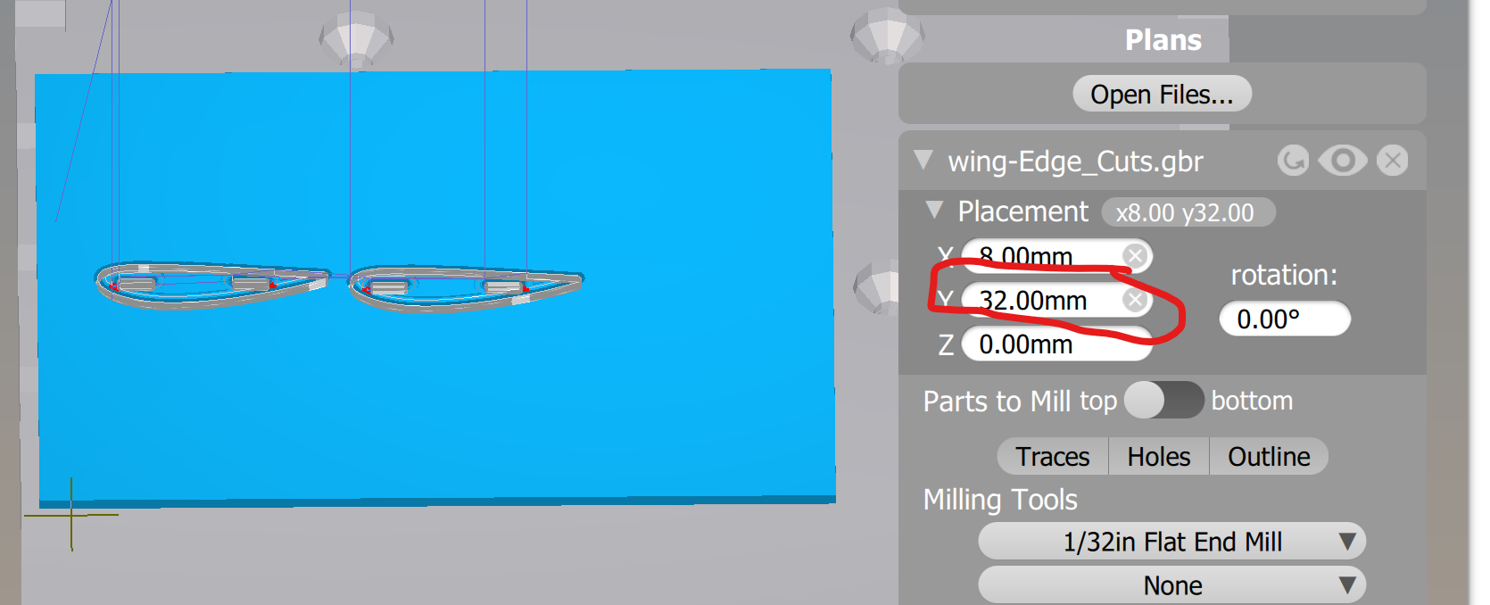
Imma use the same piece I milled last time, which means I need to offset my KiCAD plot so I don't re-mill what I had before. About 32 mm should do it. The good news is, I don't need to re-mill the spars; I just need new airfoils. Save more time & material.
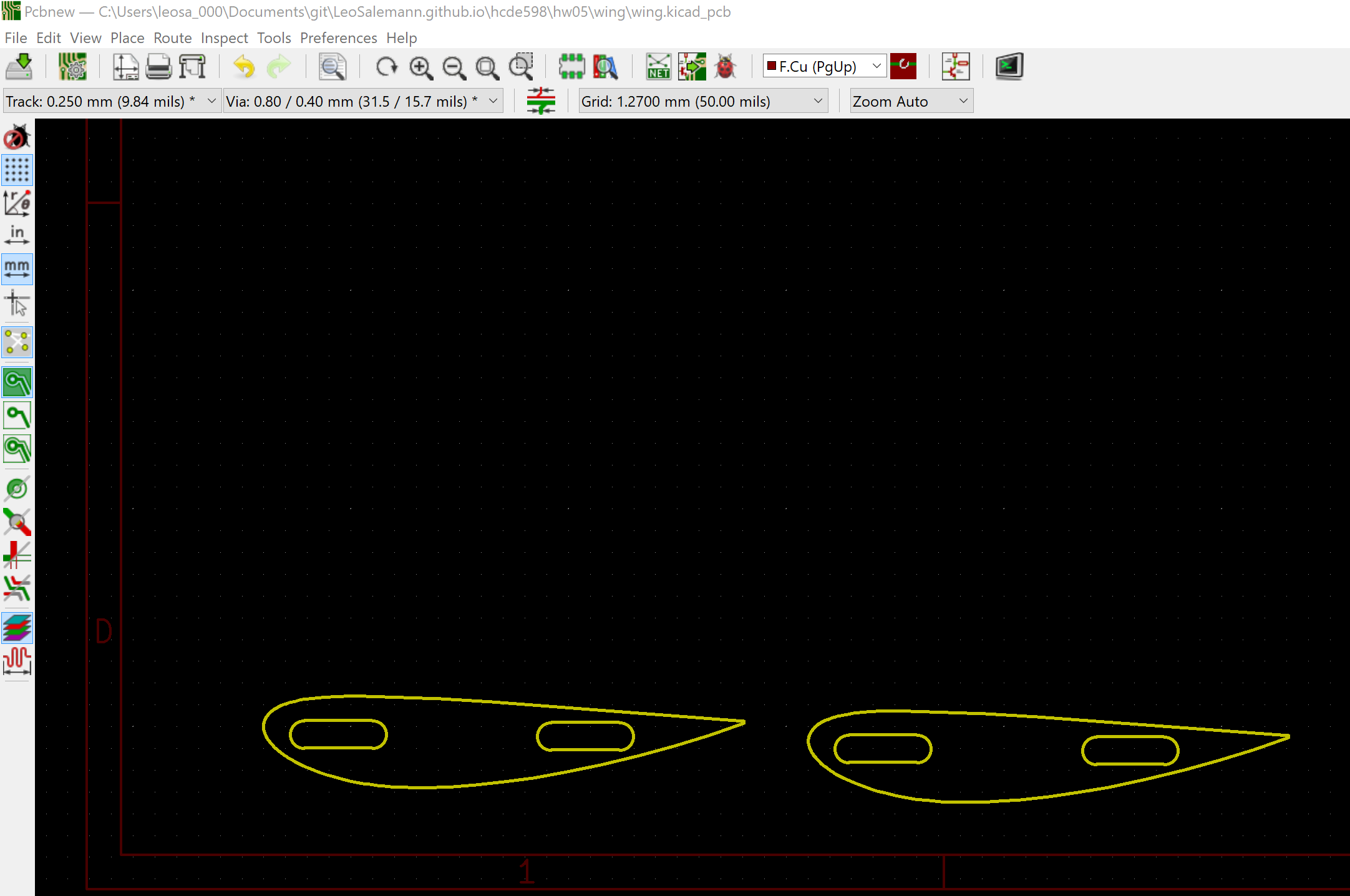
It didn't cut all the way through.
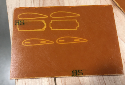
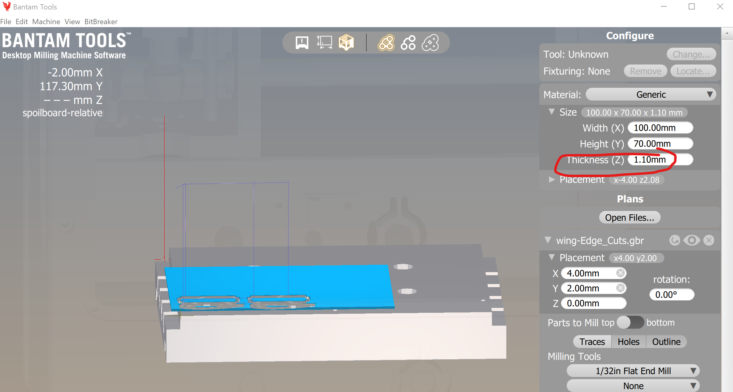
Start with a fresh FR1 sandwitch. Reload the Gerber file with all the
airfoils and spars. Set Materia Z Offset
to 1.1mm and cut again. Use the same full-tape for
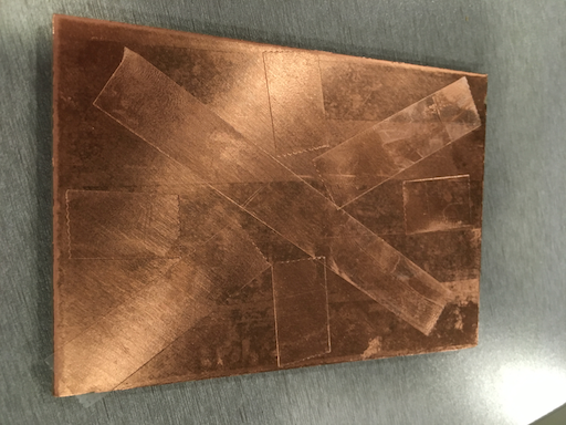
"sandwitch meat" but do a simple "Union Jack" pattern for the surface that
tapes to the aluminum bed.
Another cut-though failure! Wait a sec. I changed
Material Thickness; I should be changing
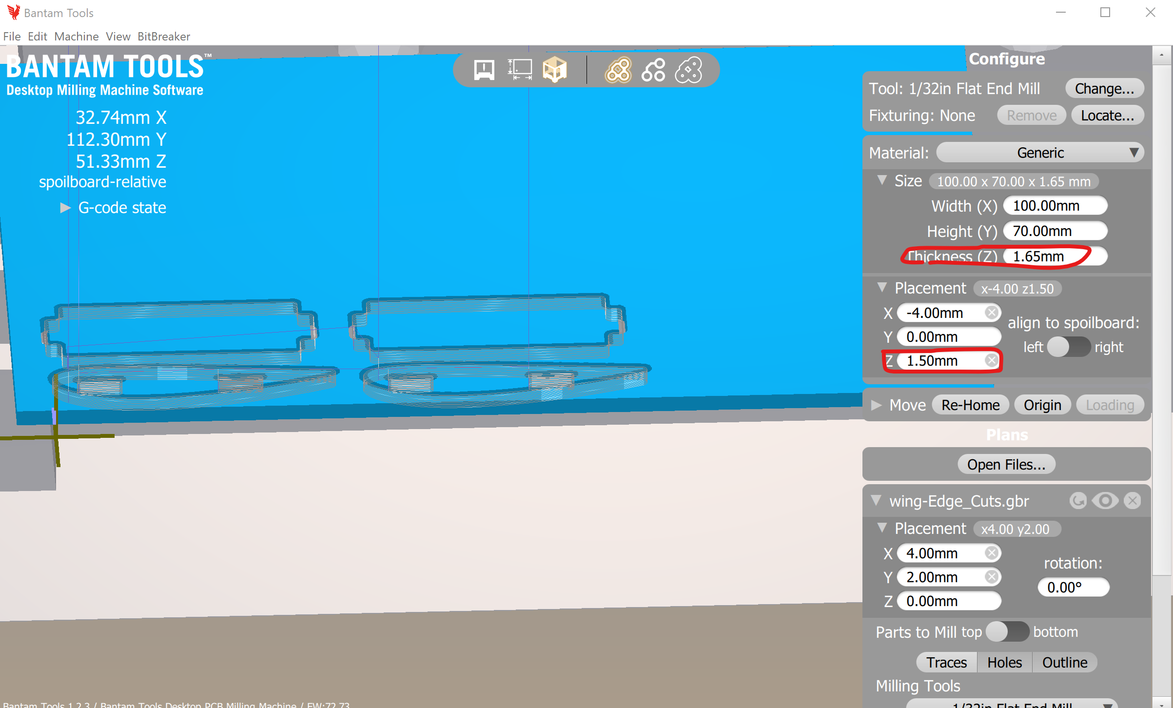
Material Z-Offest. Let's. Try. Again. Set the
Material Thickness to 1.65 (lie a little
and say it's thicker than it really is); Set the Material Z Offset
to 1.5 (lie a little and say it's not as high off of the
base plate as it really is).
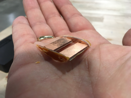
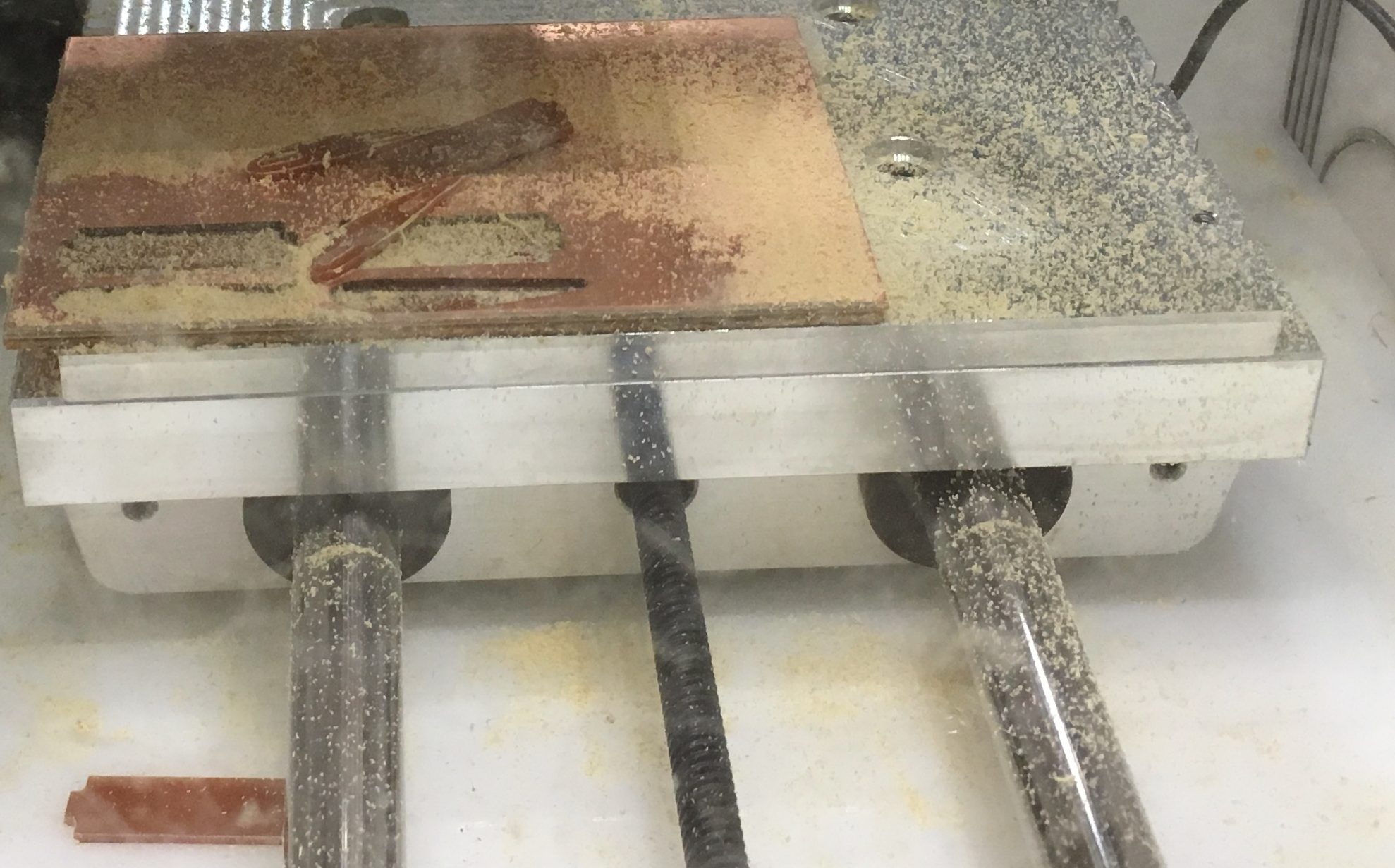
Uh-oh, loose parts. That'll teach me to try re-using the "sandwitch tape"
from a prior run.
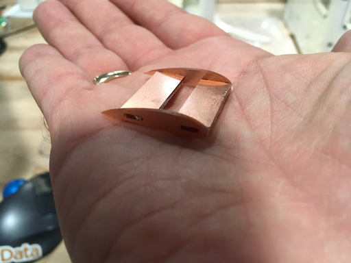
The parts came out, give or take a ding or two. They fit together, although
they're loose.
The notches are ok, the slot lenghts are ok, the slot widths are too loose.
Caliper says the notch is 1.30mm thick, while the slot is 1.37mm. Onshape
says the Slots were to be 1.6mm thick. If I set my caliper for 1.59, I can't
even fit it into the slot.
So I'm kinda flying blind. I could make a big long "fake airfoil" with a
bunch of slots, all the same length, but gradually smaller widths. Step
down 0.02 per slot maybe.
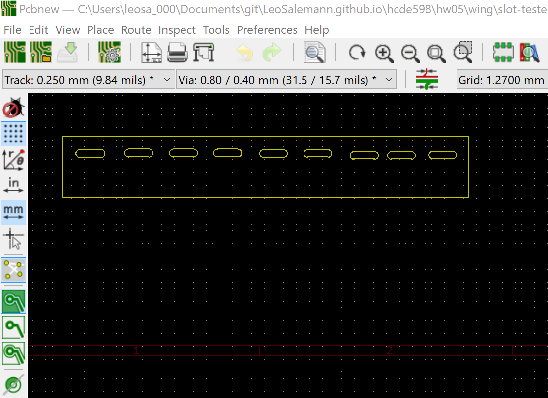
Let's get on with it. Print that slot-test from yesterday ...
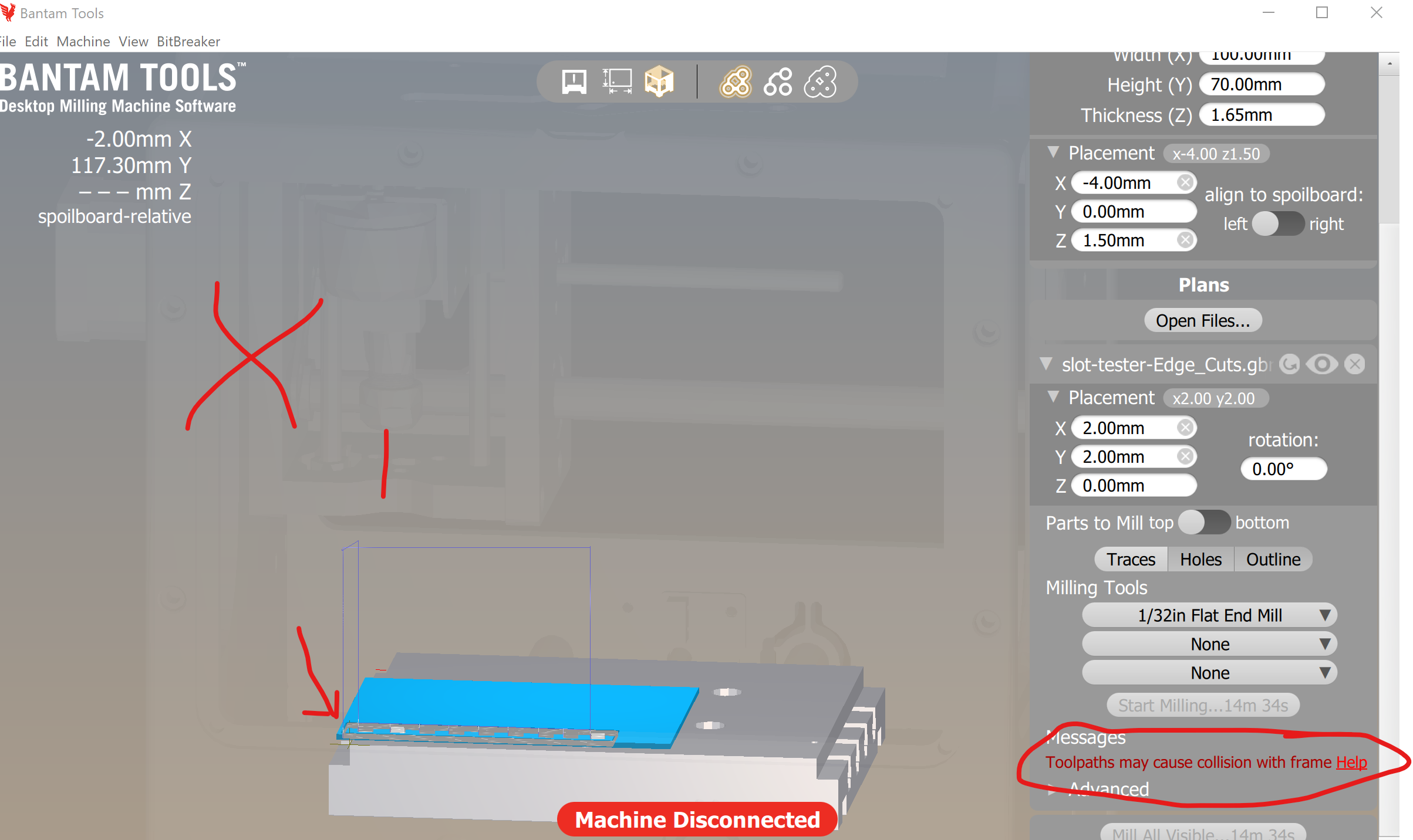
Interesting. A frame colision warning. In other words, the milling head
can't "scoot left enough" to cut my part.
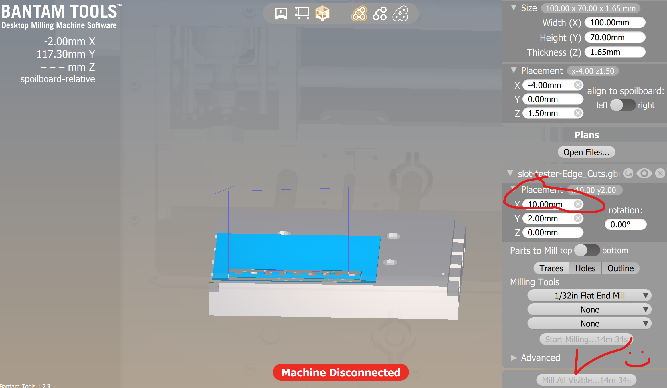
Bumping the Edg Cut Placement X-offset up to 10mm seems to take care of it.
Hm. The thought occurs that I may have been able to save some time and
tool wear by skipping the rectangluar outline and just cutting the slot
holes. Or maybe somehting I'm not considering at themoment would convince
me that would be terrible idea if I tried it. I'm just gonna let the
mill run and work on my write-up.
Oh, great; something unexpected and unfortunate happened again. None
of my slots fit particularly well. Upon closer inspection the slot
widths on the top (copper side) ....
... are visibly different form the bottom (substrate) side.
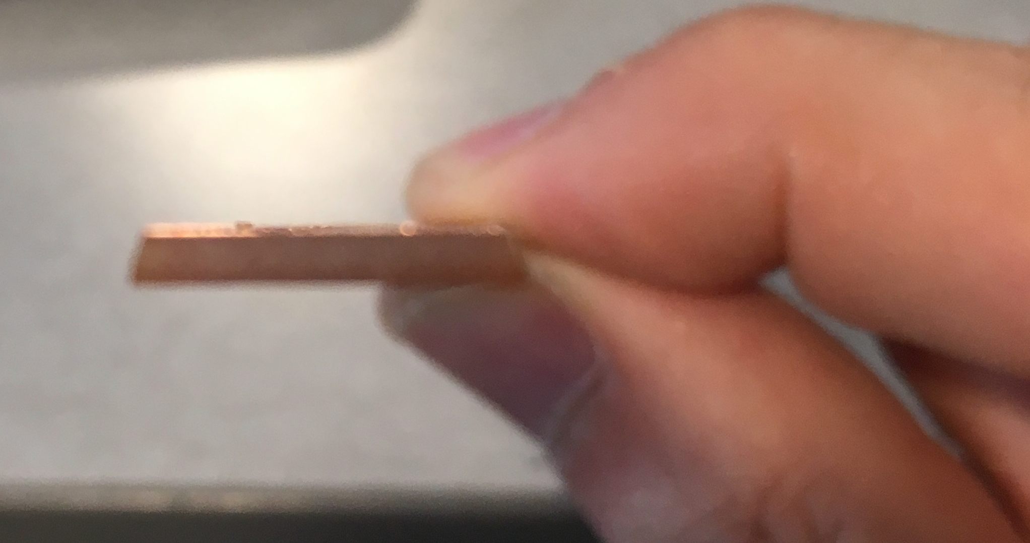
... an even closer edgwise inspection shows the cuts are
sloped instead of vertiical. I measured the end of the milling tool
at 1/32 inch (I swear I did!) but it turns out it wasn't an actual end
mill.
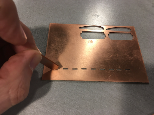
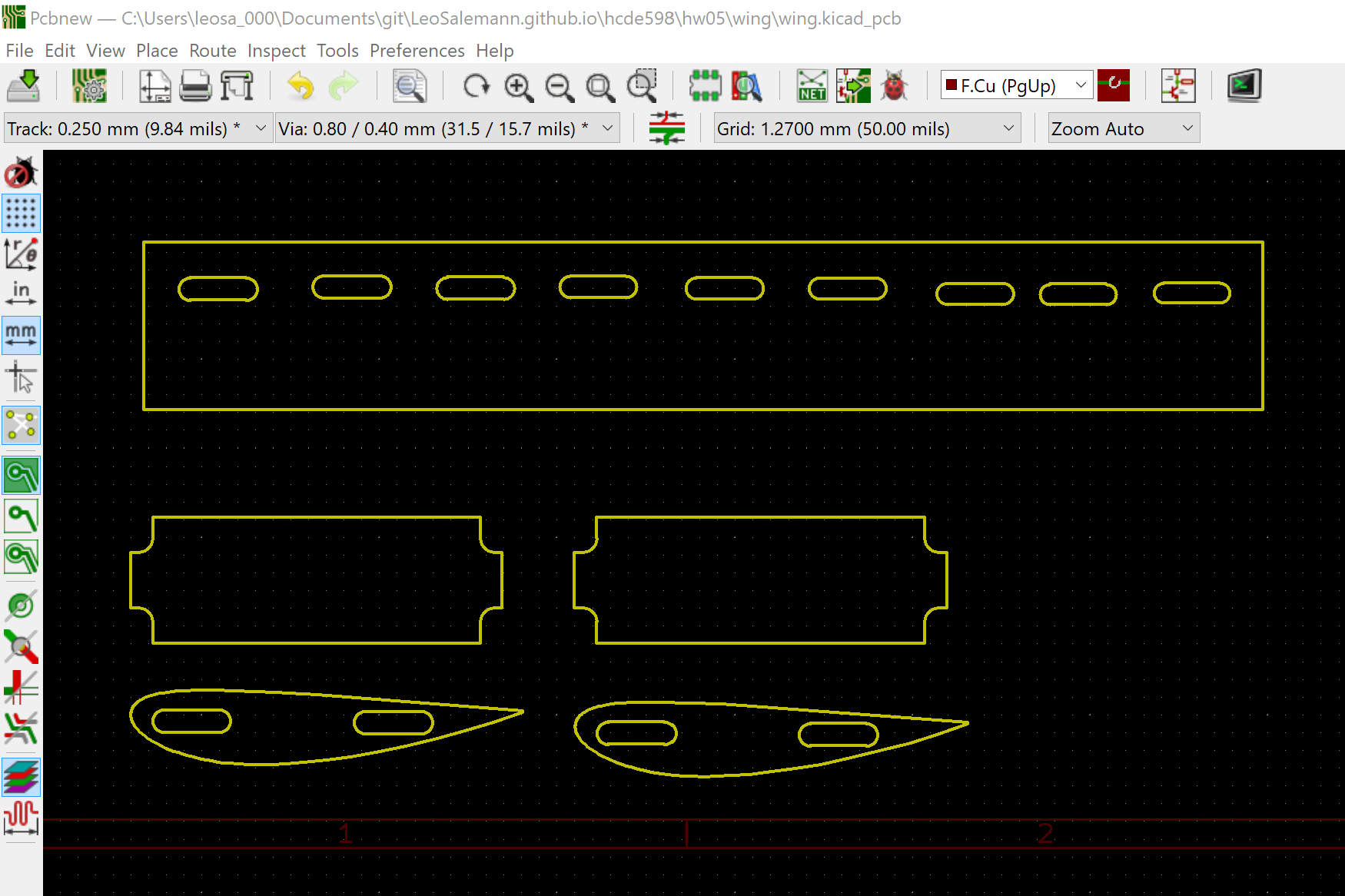
Rig up and try (yet) again. This time I'll do slots only, no rectangle.
whack the rectangle out in KiCAD, re-plot for Bantam. Add a y-offset
of 21.1 mm so the slots will land in an open spot of
my (heavily used) material.
Wait a sec. Without the rectangle, Bantam wants to cut rings instead
of holes. Need to have the rectangle, but I could interrupt the cutting
process to save some time. Back to the original slot tester.
The smallest slot holds ... barely.
Forget about Joshua's origiinal slot width. Measure my actual material
and go from there. Measure both ends of both spars. I'm getting
1.28 mm, 1.29 mm, 1.30 mm. Prior slot tester started
at 1.6 mm and dropped down to 1.4 mm
(which just-barely holds) stepping 0.02 mm each time.
What I really want to do is have a midpoint of 1.29 mm
and step it by 0.01 mm each direction.
And now, every slot is too small. I'm gonna finish this write-up, then
probably screw it and glue it.
AGAAIN !?!?!
It Kinda worked

How Would I do Better?

DAY FIVE: Doing It Right for a Change (I Hope)




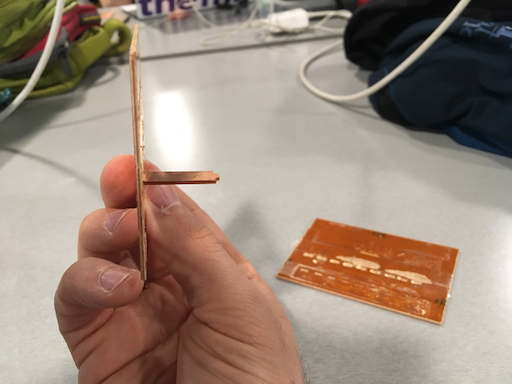
Slot Test 4 (Seriously?)

