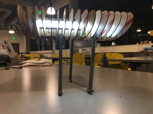
Leo's Assignment 3: Lamp!
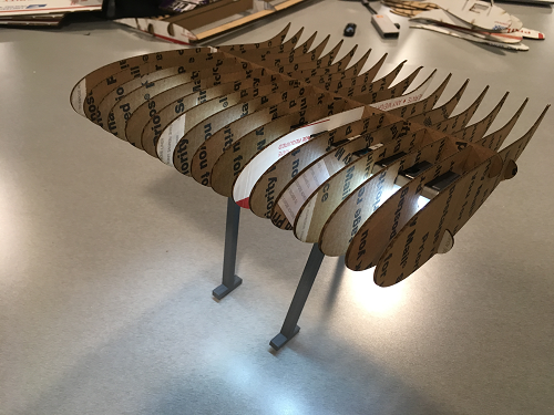
Here is all the documentation for assignment 3!

Here is all the documentation for assignment 3!
Available on github.com at https://github.com/LeoSalemann/LeoSalemann.github.io/tree/master/hcde598/hw03
Got some family commitments this weekend, gonna be tricky to fit in multi-hour print jobs. Gotta keep things simple for a change. Main thing to keep in mind is to budget about an hour print time for each inch of "boundig box" for your print. In other words, something 6 inches across would take about six hours.
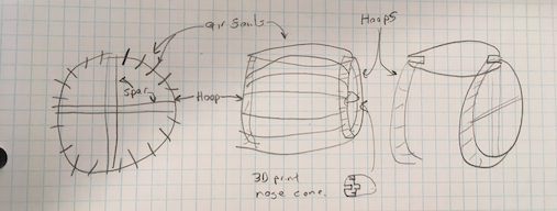
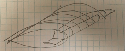
If I take my airfoils and rotate them into a hoop, I'd have something like a jet engine. I could have a 3d-printed hub in the middle to hold the "turbine blades" .... time to sketch.

Ok, I can print a ton of thin cardboard symmetrical airfoils similar to Homework 2. If I can figure out how to score my spars so they bend into a hoop -- or, use strategically-flimsy material, I'll have my jet engine. Some rigid mateiral in a cross could keep the hoop together. A cone-saped "spinner" would be a good 3d print.
To really make it look like a jet engine, I need the front (or top?) of the lamp to look like this:
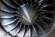
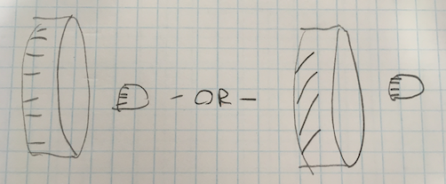
Must .... resist ... urge to make ... complex .. parts!!! Ahem, ok. My blades can be simple rectangles, laser-cut from twistable material. The nose cone could have vertial slots, while the hoop has slots at an angle. Or just keep them straight, and the light will probalby shine through better. Probalby stick with no-twist, so I can re-use my USPS cardboard and slot measurements from Assignment 2.
Probably a central I-beam with a couple cross pieces.

It just-so-happens my lamp-innnards are actualy an LED strip light. Furthermore, it just-so happens to fit perfectly on my Assingment 2 wing.
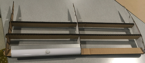
If I replicate a bunch of ribs, I can hopefully create some nice light interplay.

I have a first-world problem. My lamp actually comes with an adhesive mounting system that will work perfectly with my wing ... no 3D printed brackets required.
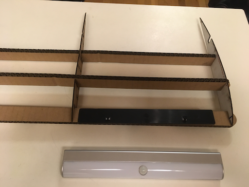
What I can do though, is 3D Print some kind of struts or feet, to get my lamp off the desk. Try for a "upper wing of a biplane" look.

So these struts are going to reach up and clip onto the wing. Maybe the thin arifoils; maybe the thick spars. I'm going to need to 3D print a slot tester. One way would be a simple block with two slots cut at right angles. This could form the "head" of the strut that clips onto both the airfoil and the spar.
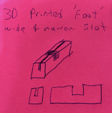
Easy to print ... but will I get it right the first time? Maybe I should 3D print a version of by gauge. I can make it thiner to use less material (and time). Also, these ideas are coming rapidly when I'm away from my sketchbook, so switching to post-its.
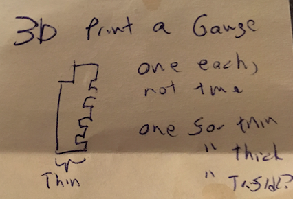
Cool, two parts to 3D print and some incremental mods to my Grasshopper files. Given the long lead times, I need to sequence things.
Shrunk down my Assingment 2 Gauge down to 1 inch by 0.5 in. Besides the input siders I used last week, I had "configuration sliders" stashed around to control overall gauge width and height, as well as the size of THE NOTCH. Parameterization is starting to pay off.

By selecting an element upstream of my original output, I can bake one gauge instead of two.
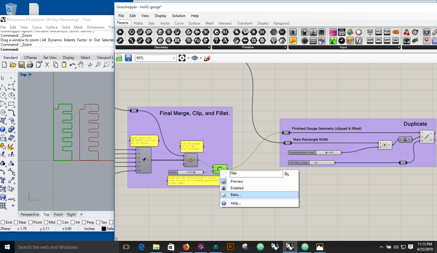
Extrude and Cap seemed ok, but I'm worried about how it's rendering hopefully just a wierd artifact with my VM's virtual graphics card.

Tried Dremel DigiLab, couldn't see anything. Tried Contangent, it prompted me to convert mm to inches, then looked fine.
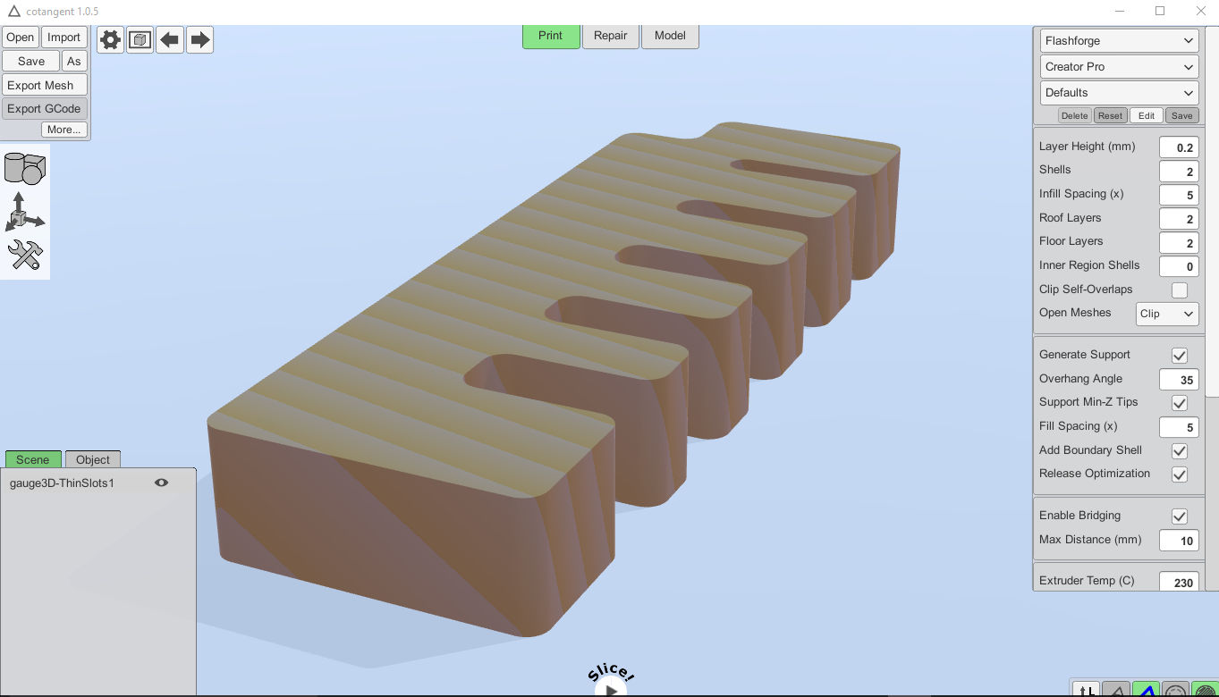
Had trouble runing Dremel DigiLab last night, but got it going today. Looks like my 3D Gauge works there too. Looks like I'll need to use Cotangent to convert units, then Digilab for the final printing. Maybe I could print through Cotangent, or do unit conversion with DigiLab, but right now I'm in a mood to go with any workflow that ... works, not necessarily the leanest one.
Turns out use of glue is forbidden, so I really shouldn't use that self-adhesive bracket that came with with my lamp-guts. Gonna need to develop a bracket-thingy after all.
Last night's big reveal was that I can't use the adehive strip, so here's a sketch of a 3D-printable lamp braket.

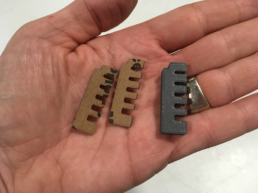
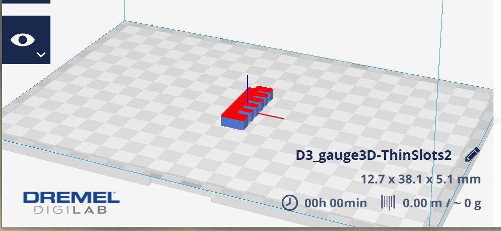
My Dremel DigiLab pic from last night says my gauge is going to be 12.7 x 38.1 x 5.1 mm big. The thinner it is, the faster it will print. Checking a 3D Print Test Piece in the MILL, I'm seeing 3mm as a baseline thickness (below.) I'll call 5mm close enough and start printing.

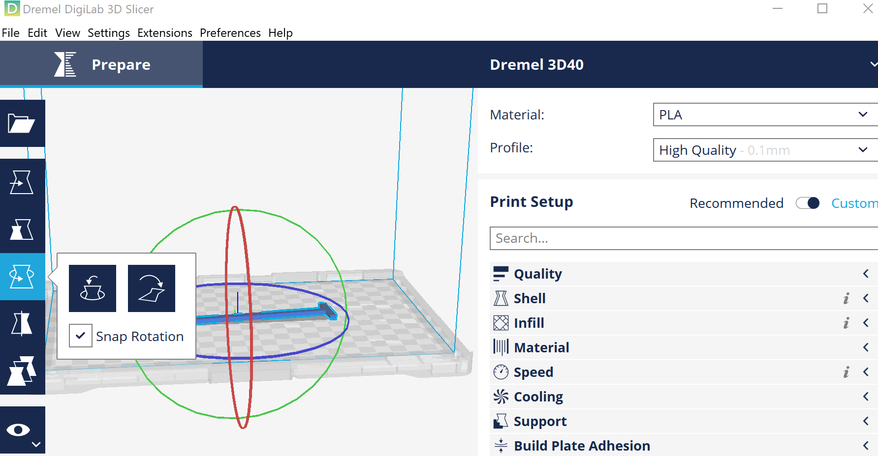
Opened my 3D gauge in Dremel DigiLab again, chose Orientation then Lay Flat, with Snap Rotation turned on.

Go to printer, start with Level.
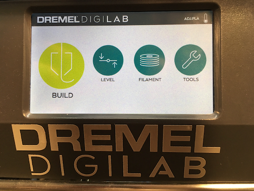
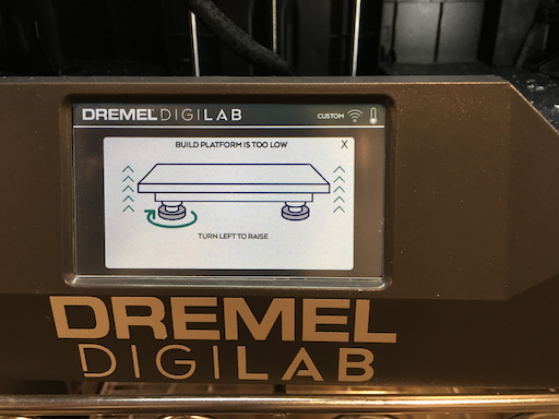
Got prompted to turn a couple knobs.
Go through the change filament procedure. Good thing I did, I can see how it purges the old material from the nozzle.
Selected PLA as filament type. Set nozzle temp to 235 per slack instructions, all other settings left as default. Got some kind of warning that says Extruder range 190-230. All I can do is click Accept. Ah, back at filament settings, pull the nozzle temp down to 230. Later on, Jo Jo let me know you can go into custom settings to get past 230 on nozzle temperture.
Clicking Build now. Can't find where to transfer files from USB onto printer. Check the Tools page. Found an option to Pre-Heat. Seems like a good thing to kick off while I continue figuring out how to copy form USB.... aaaaand .. now I'm stuck until pre-heat finishes.
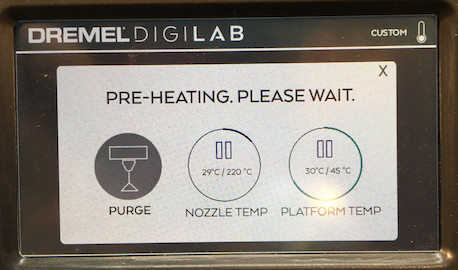
Also gotta apply glue, hope the bed istn't too hot. Nope, we're good.
Ah, found the MILL Dremel 3D45 Ideamaker checklist. The machine will copy files from my USB. Pre-heat seems to still be pre-heating ...
Exit (i.e. gentle rage-quit) out of pre-heat, start an actual print ... nothing. Wrong file format? Object too small? Back to DigiLab software.
Okay ... the MILL checklist says to use .g3drem files instead of gcode. So .... how do I convert? Talked to MILL staff, they said switch the DigiLab software settings to 3D40 instead of 3D45.
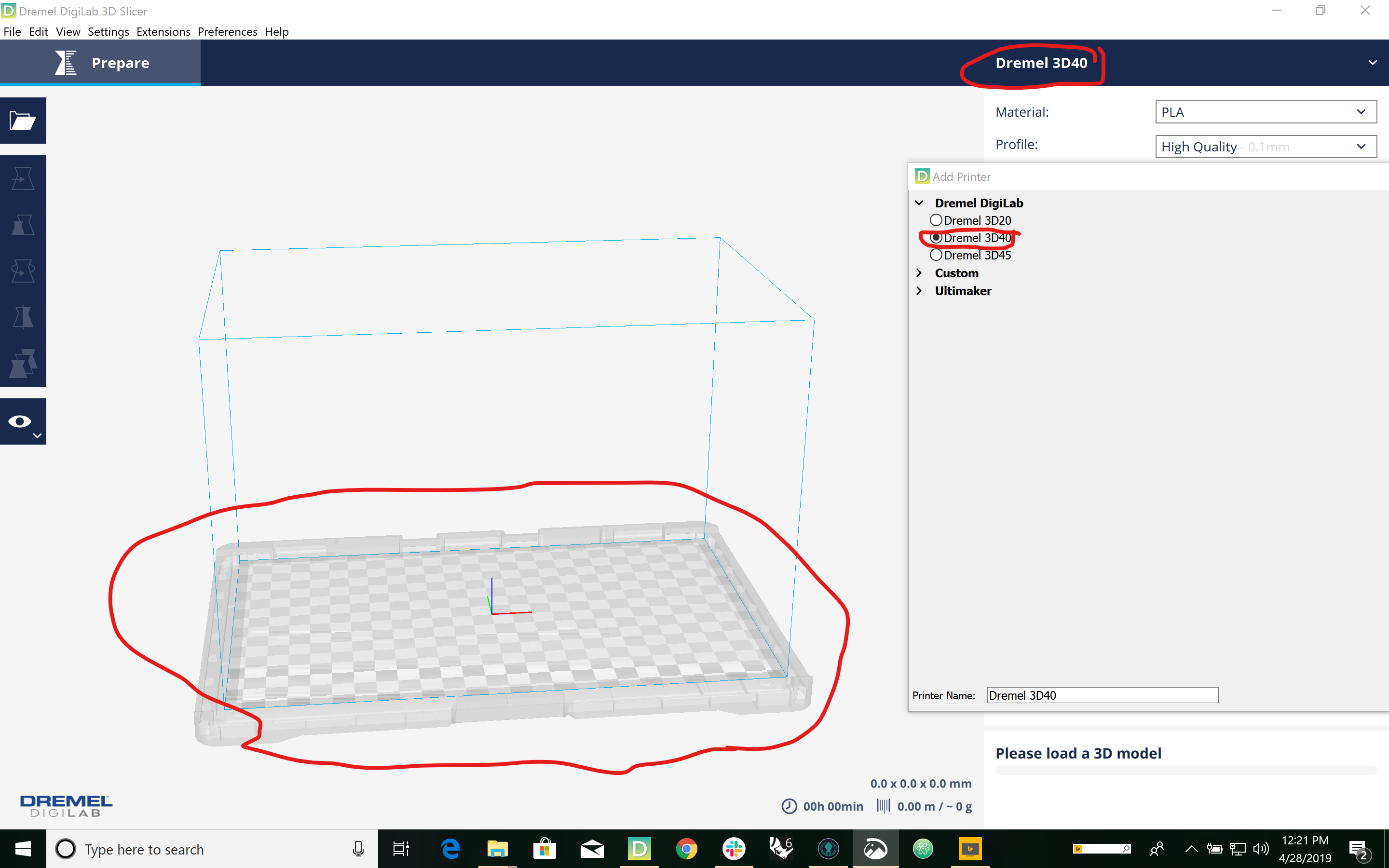
Nothing seem to be coming out. Nozzle temperature was too low, so I stopped the build. Went back to Filament on the touch screen, then View Filament Settings. Nozzle says 230 like I wanted. Try 235; still forbidden.
Back to preheat, try Purge Nozzle. Purge isn’t doing anything, try Change Filament. Still nothing coming out. Got help from UW MILL staffer Jo Jo, she had me use a new printer. Scrape the Build Platform clean, Re-do the leveling process, kick off a print, and wait with mild anxiety untill ....
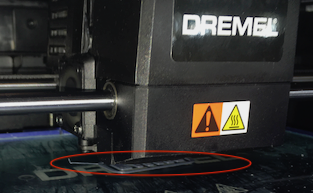
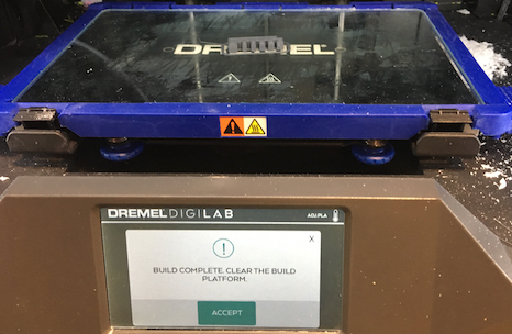
The printer threated it would take 29 hours, but finished in about 45 min.
Routine and uneventful (for a change). Used 25 speed, hundred power, hundred frequency. Also set document size to 21 x 15.5

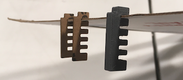
Like the 3D printed one, the tightest slot is the only one that works. The differences is, the lascercut slot is noticably looser than the 3d-printed - it just barely holds. Tempted to do another round, taking the tightest slot and making it my new middle.
Okay ...
I know the slot thickness I need for 3d printing. I need to measure the lamp guts and make the actual bracketry. Forgot my sketch book at home, so we're back to post-its.
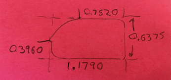
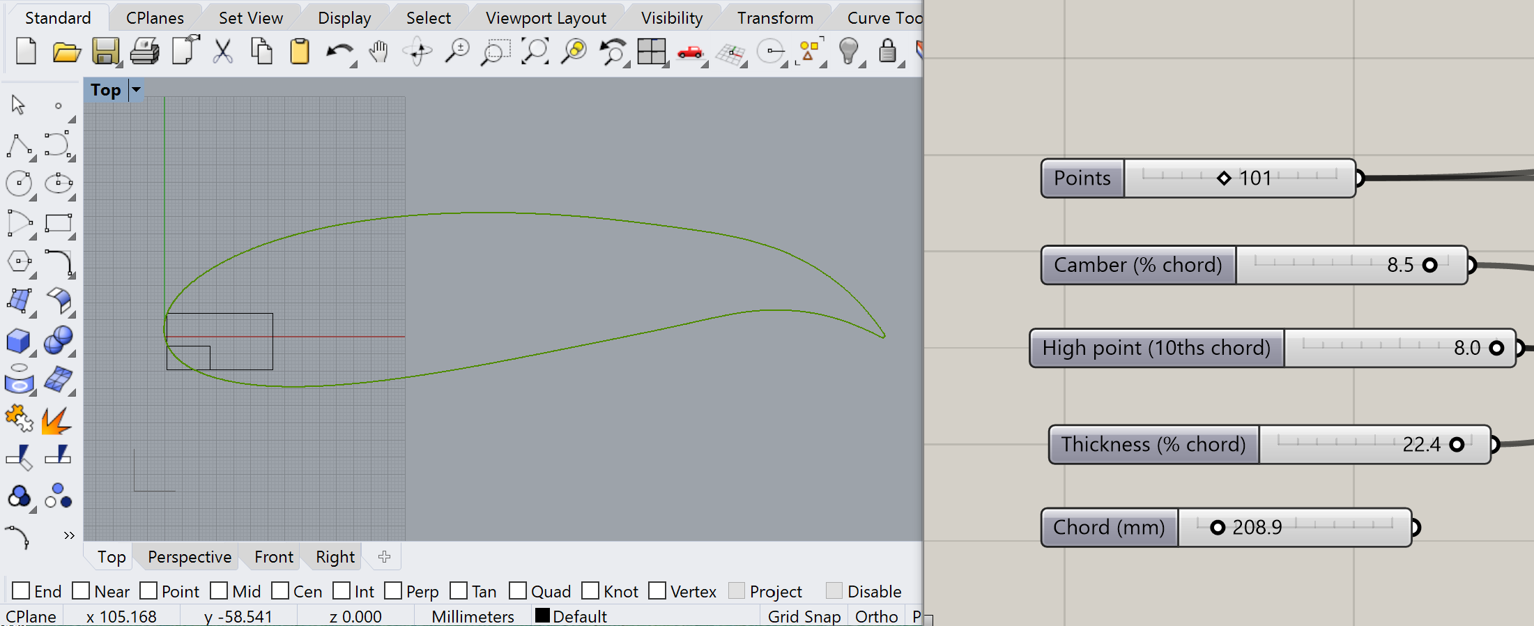
Okay, now with these dimensions, I can go into Rhino and draw up a couple rectangles - one for the main bounding box of the lamp guts, another for the rounded "cut-out" in the upper-right corner. Now is a good time to try out Dr. Gareth Paterson's Grashopper NACA airfoil generator.
Hmm ... Dr. Paterson's Airfoil generator requires it. So, re-doing the lamp-guts dimensions in mm, I have 30.76 x 16.4.
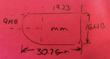
Using the Rectangle comand at the Rhino prompt, I can make a rectangle in the exact size I want. On the Grashopper side, I can fille with the NACA inputs to get compatible airfoil shape.
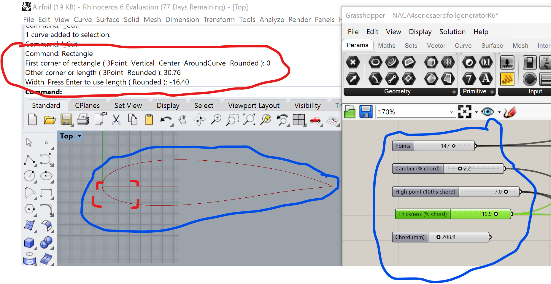
Looks kind of dull, also not sure how the curve of that airfoil is really going to line up with my lamp guts. Add another rectangle, tune the NACA inputs and ...

Let's print this and try it out. This time 1mm = 1mm

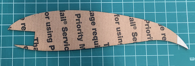

The lasercut worke and fits nicely. But to really be an interesting play on light, the lamp should be embedded deeper.
Time to trace, measure, and think again. The rounded corner isn't a single readius, more like a flat line with a bend at each end. Looking closer and running my fingers over the curve,I think the radius being used to round the 90 degree corners might also be used for the diagonal.
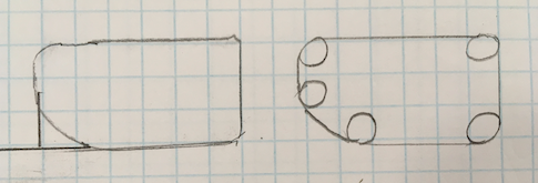
Okay, back to Rhino, try some rounding-radii, and eyebal it. Use InsertControlPoint to add a fith point to the rectangle. Move points by left-click and drag. Delete that smaller rectangle. Move the reshaped rectangle to a more interesting part of the airfoil. Ended up with this:
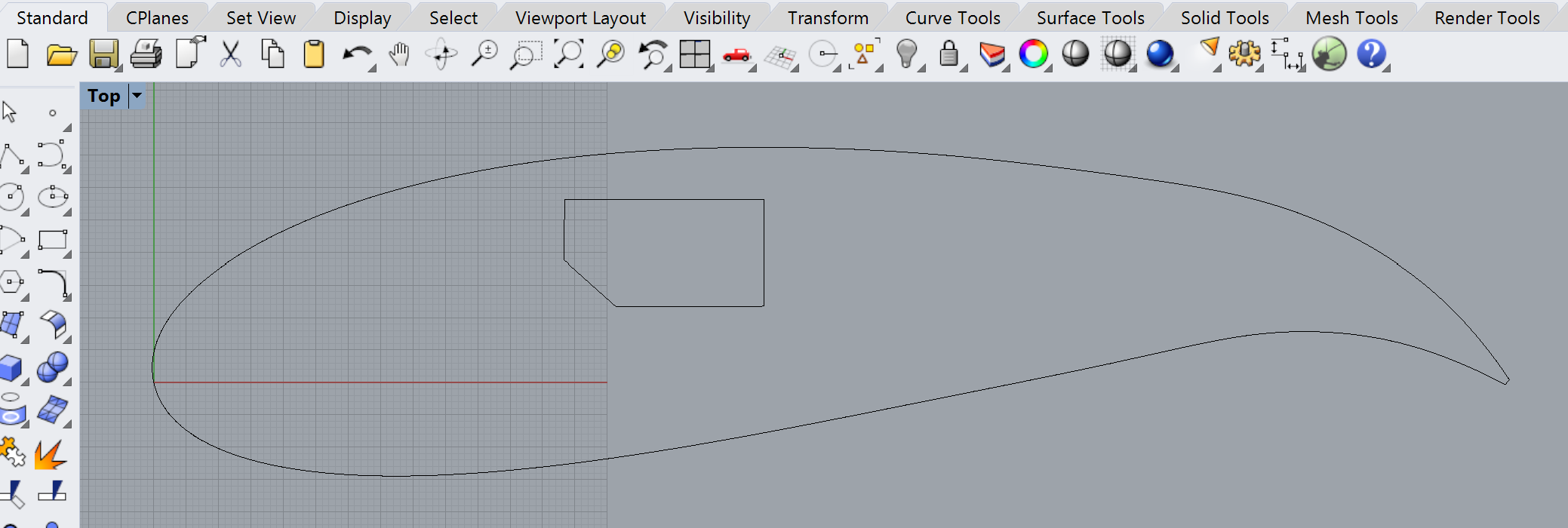
Time to export and print again. Lamp fits snugly with minimal gaps.
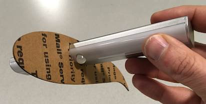
Sweet! A dozen or so of these "lamp hole" airfoils, a solid one at each end, a few spars to hold it all together, and I've got my lamp! The 3D printng will come into play as "struts" to lift the wing-lamp off my desk.
Now that I know what to print, I should CAD it up ASAP, to max out my available lead time for printing. I'll stay in the same "inch world" that I had with my gauge, since I'll be dependnt on the winning gauge slot.
Pull up the gauge generator again. This time, I just want the rectangle for the upper slot. Find it, bake it into a new clean Rhino file.

Now, build a strut. A simple upside-down T.

Extrude Curves 0.1260 inches (about 3 mm).
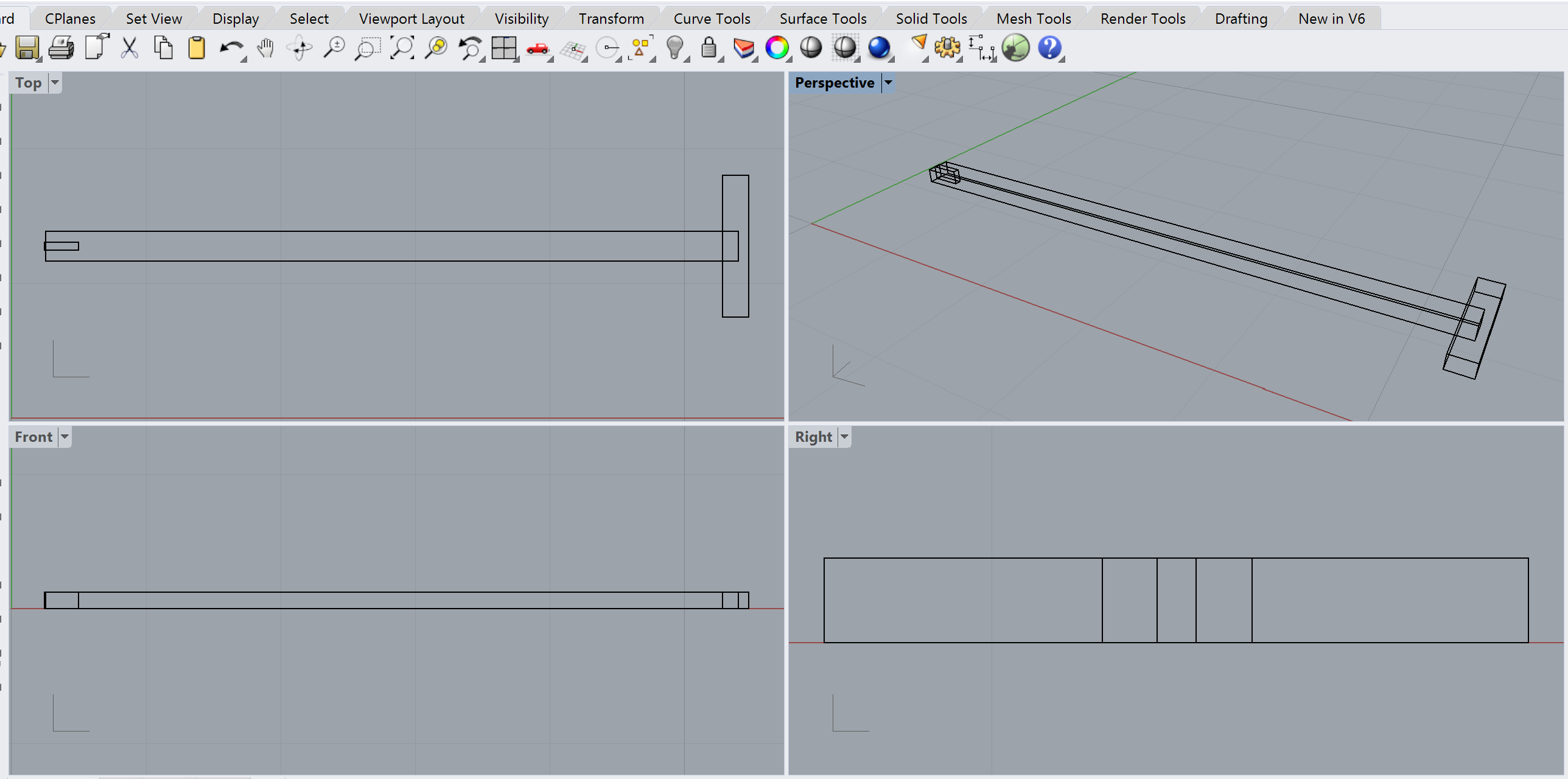
Cut the slot into the strut, merge the "foot." BooleanUnion and BooleanSplit seemed to get it done, but it was a bit tedious to click and drag the "cutting slot" away from the main strut. Kept coming off in bits and pices.
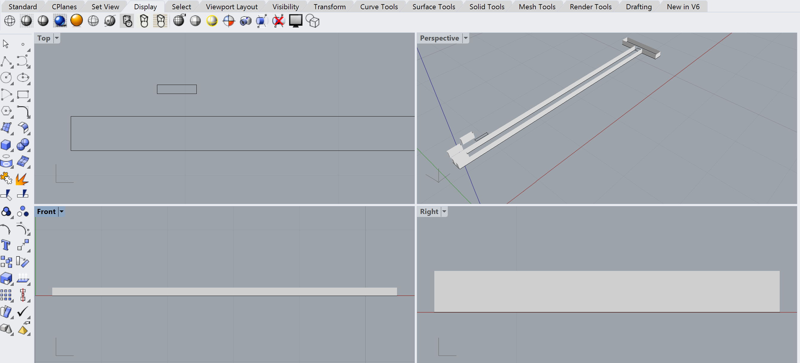
Delete the debris, cap what's left, and I think I'm ready for Dremel DigiLab.
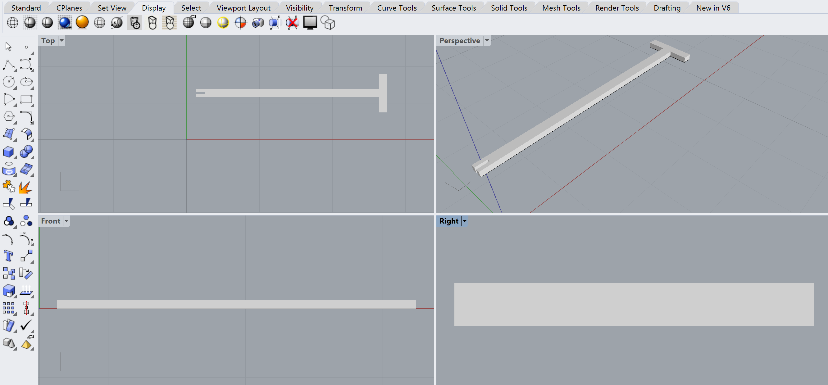
Export to STL, pull into Cotangent. Hmm, this time, it didn't prompt me to convert to inches. Back to Rhino, set both Layout Units and Model Units to inches. Export to STL, load directly into Dremel DigiLab. Doesn't help. More scale-hacking, this seems to have worked:

Okay, we got a 3D print ready to start first-thing tomorow. Best we can do now is cut more Airfoils with holes.
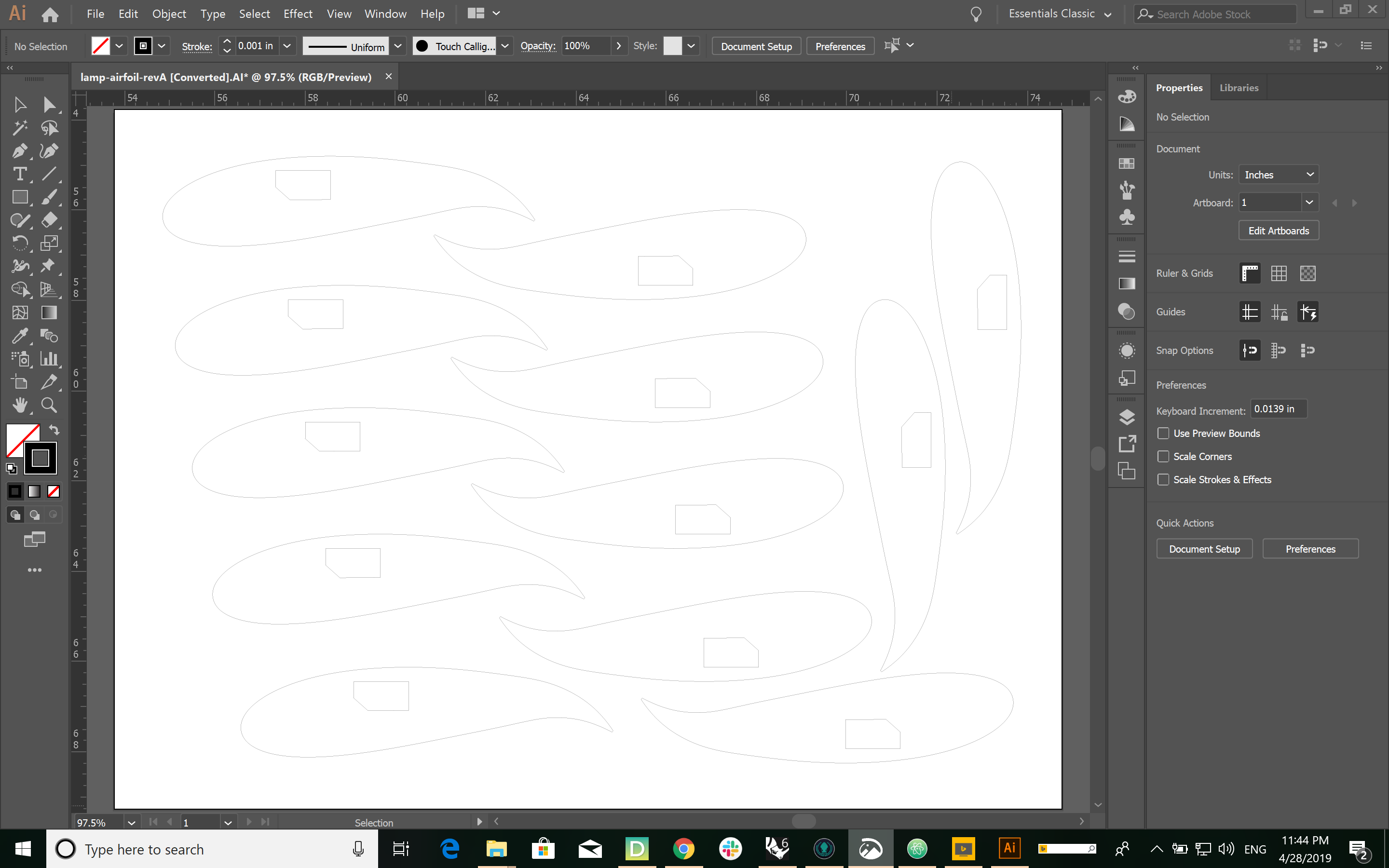
Well this is embarrassing. I forgot to add slots for spars. So I have a dozen arofils with lamp-hole ... and nothing else.
Okay we got that strut in STL form from last night. Pull it up in Dremel DigiLab, generate some gcode, and start a print.
As with the gauge, do a Rotate > Lay Falt > Snap rotation.
Found a printer that said it just completed a build, this is a good sign. Start with change filament. Prior film it was the same color, so just have to time it right.
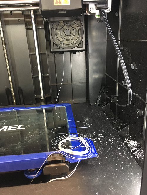
Tried custom settings instead of PLA, got the nozzle to 235, but build platform temp ended up at 45 isntead of 35. Once the build was underway, filament wouldn't stick.
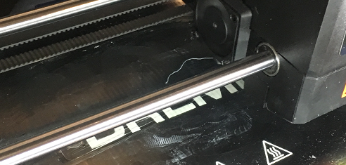
No I'm spooked so I'll stick to PLA default settings, changing only the nozzl temp to good ol' 230 deg. C. Same value that worked for my gauge.
Talked to a UW MILL staffer Anita, she sent me to another printer. This one worked the firs try.

Cool! By the time I finished writing this up, my print was ready!

Crap! I broke it while scraping it off the build platform.
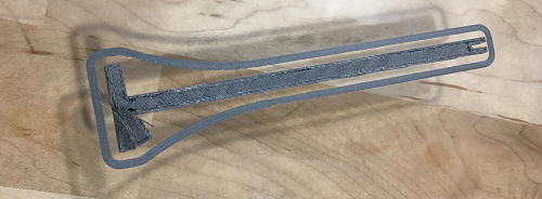
That won't keep me from being a good citizen, though.
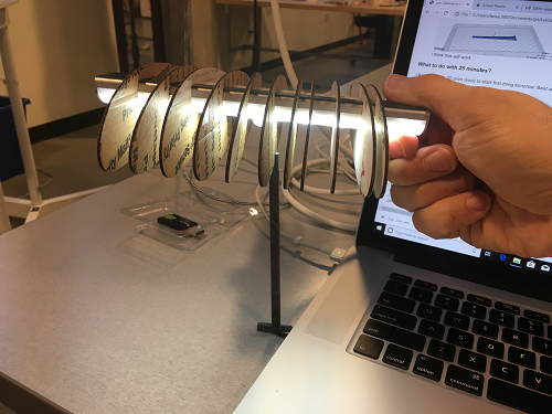
And I can still do some fit tests with it.
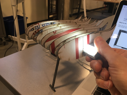
Y'know ... I think this wing looks better inverted.
Gotta keep that printer running to manage my lead time. Pretty happy with the slot; would be nice if it could be thicker. Maybe a hotter nozzle will make it stronger and look better?
Talk with MILL staffers about my bed adherence issues. Livia suggests a higher bed temperature. I'll probably try to crank the nozzle up to 235 as well.
First-off, get back into Rhino, see if I can extrude higher. Looks like I shoudl delete the polysurface, keep the polycurve, and re-extrude.
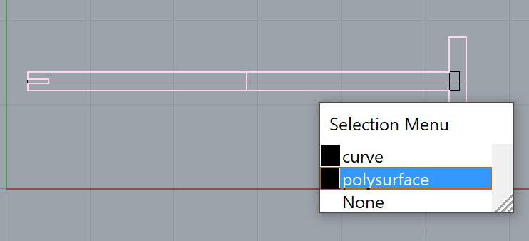
Also had to go back to Grasshopper and regenerate my rectangle for slot cutouts (again). This time I'll keep the 2D gauge around so it's easier to re-use.
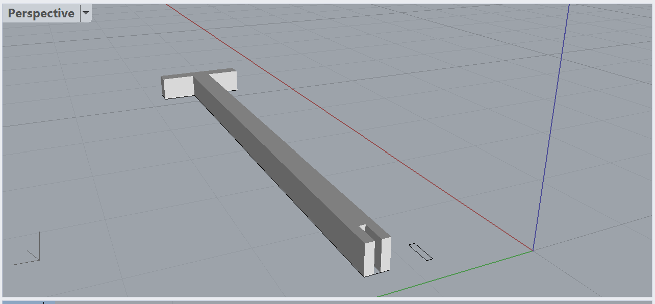
Need two copies of the strut for a total of 3. Going to try and do that in Dremel DigiLab. Cool! All ya gotta do is open, move and/or rotate, then open again. Each time you open an STL, you get a new copy of the object. At first I wanted to rotate one to get an alternating pattern, but it got hard to rotate a perfect 180, so I kept them all facing the same direction.

Looks like a 2.5 hour print ... gotta queue this up fast. This time I'm going to use custom filmaent settings instead of PLA defaults. Going for 235 deg C nozzle and 45 deg C platform. Hoping that will help the filaments bond to to eachather for a stronger part and a smoother look.
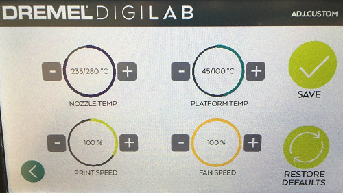
Off to a good start. Back to writing & lasercutting.
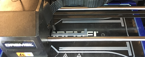
First thing I need is a good slot width. Back to the gauge.
First off, record my setting before I do anything The settings I have now are crucial to successful 3d-printed slots. Copied them all up to the machine settings section, but still feeling paranoid so I made a backup copy of the grashopper file as well.
Right, then. Back on Day Four I discovered my smallest slot-width was still too big for USPS cardbaord. So I'll make the top width the new middle. Slot size delta is subtraced from the two numbers above the middle (i.e. caliper) slot, and is added to the two bottom ones. eplicate the "slot math" in Google Sheets so I can see all the values.
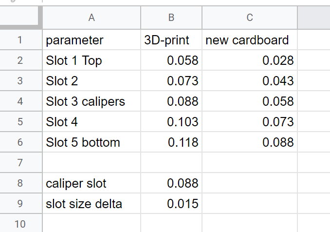
Run the Guage through the Bake -> Export -> print workflow that I used exhaustivley in Assingment 2. Turns out Slot two is the best fit this time. Based on my Google sheet, it's 0.043 inches.
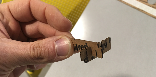
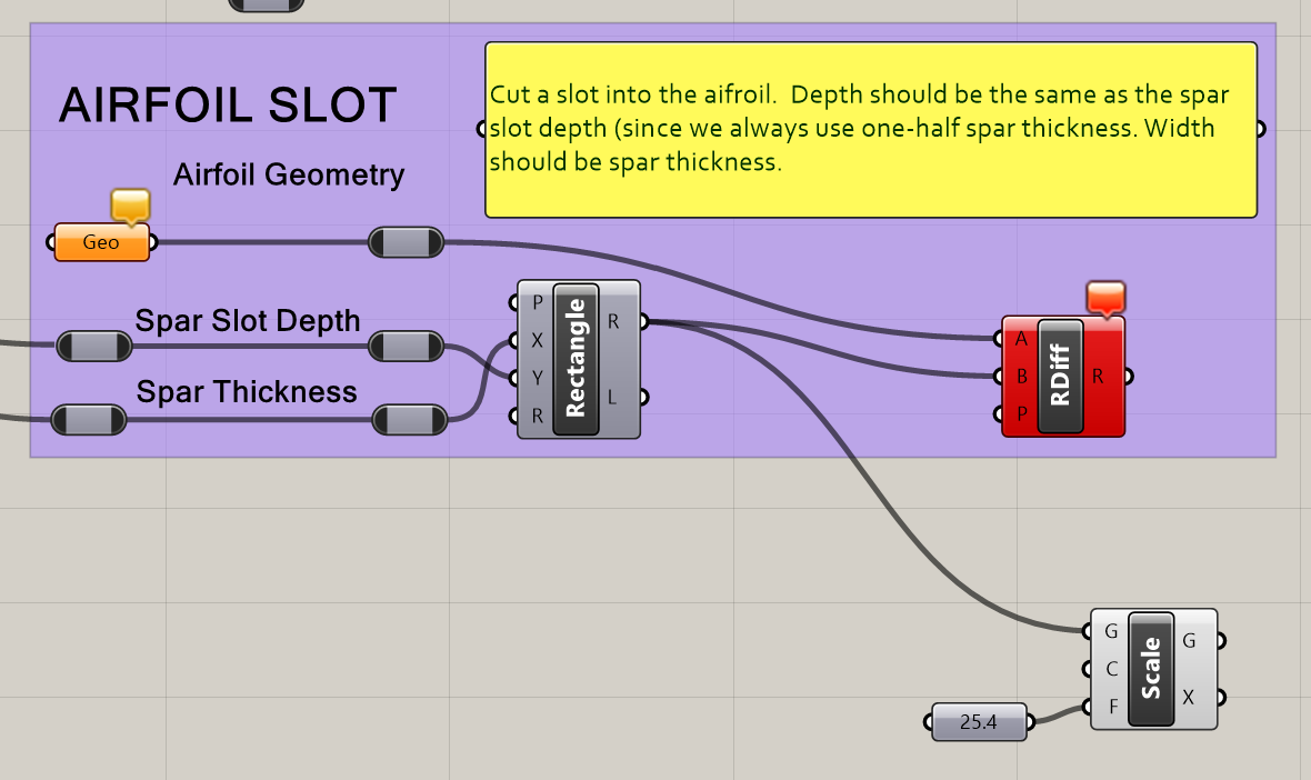
Okay, I have a good slot width (0.043 inches) and a wing spar generator that also operates in inches, so I can make a spar now. The tricky part is the airfoils -- those are in millimeters. Path of least resistance is probalby just scale my slot by 25.4 when I bake with the airfoil. One more component on the AIRFOIL SLOT module of the spar generator.
Let's stay in inches for awhile. Use the slot width I just figured out, eyeball a good wingspan based on the size of my led strip, adjust the spart height until it looks good. Full parameters are in machine settings, highlights are below.
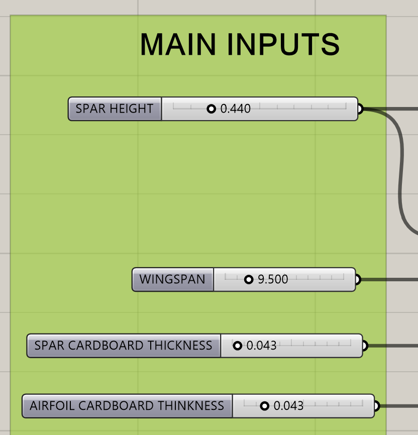
And it's a beauty.
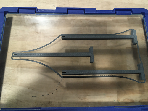
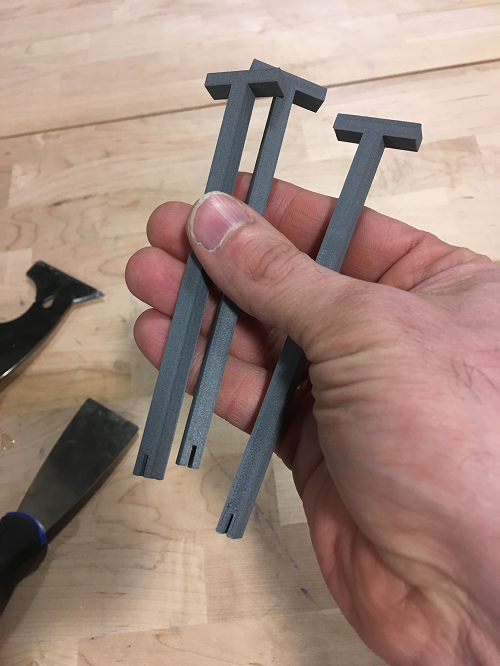
Managed to pull them off the platform safely.

Struts fit, my lamps a semi-workable sitance above the desk. I could almost stop here ... nah.

Added a module to the spar-gen grasshopper

Adjust the spar paremeters.
Print and check. Size & slots were good, but spar should be made thicker.
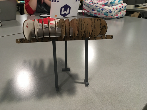
The first spar bent too much during assembly, let's make one 2-3 times thicker. Go from this.

To this (also made the wing span a half-inch shorter).

So now we have ...
Should have done this a long time ago. Add a scale component to the end of my spar generator. Scale everything by 25.4, the vlaue Rhino uses when you mess with Layout and Model Scales to convert inches to mm. Bake the output next to my airfoil and hope it all works out.

Move (with mouse) and Copy the airfoil. Also use Mirror to flip the "lamp hole" around. Them move and rotate with mouse.
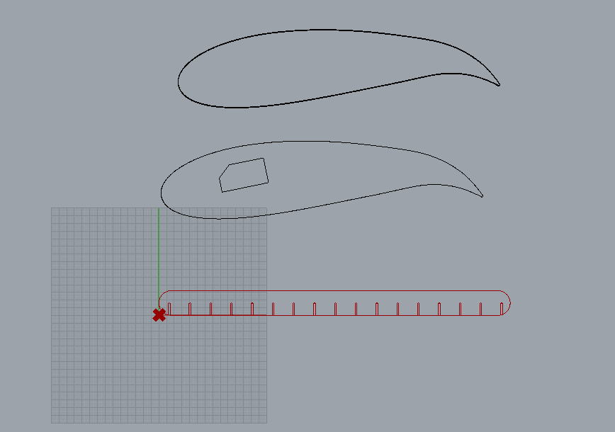
More bakes and moves. Also bake some spar slots. Had to add one more "scaler."
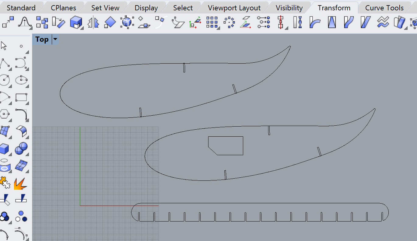
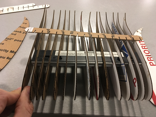
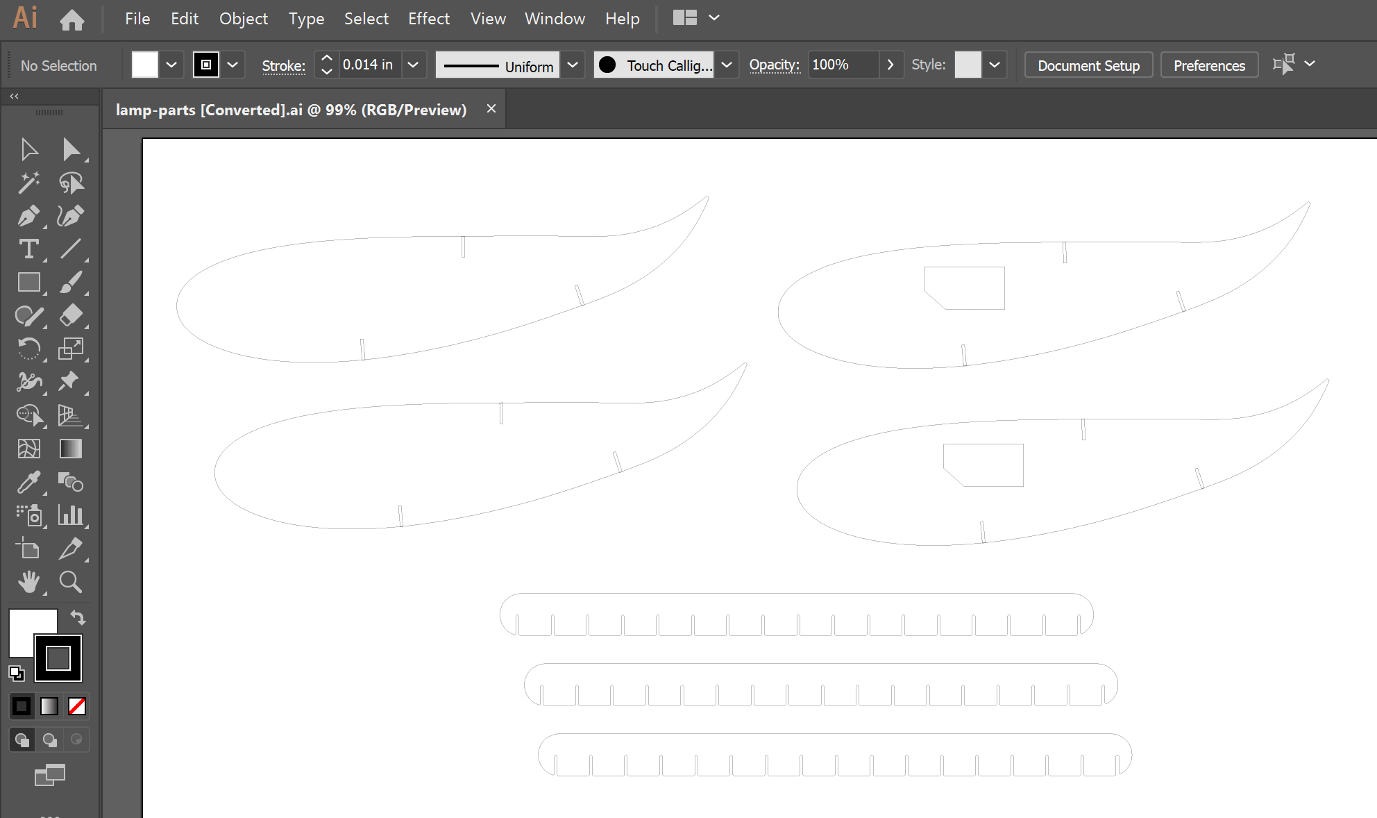
When all was said and done, it took 3 Illustrator files spanning 18 airfoils and three spars.
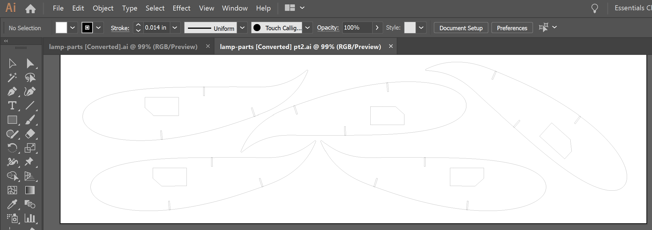
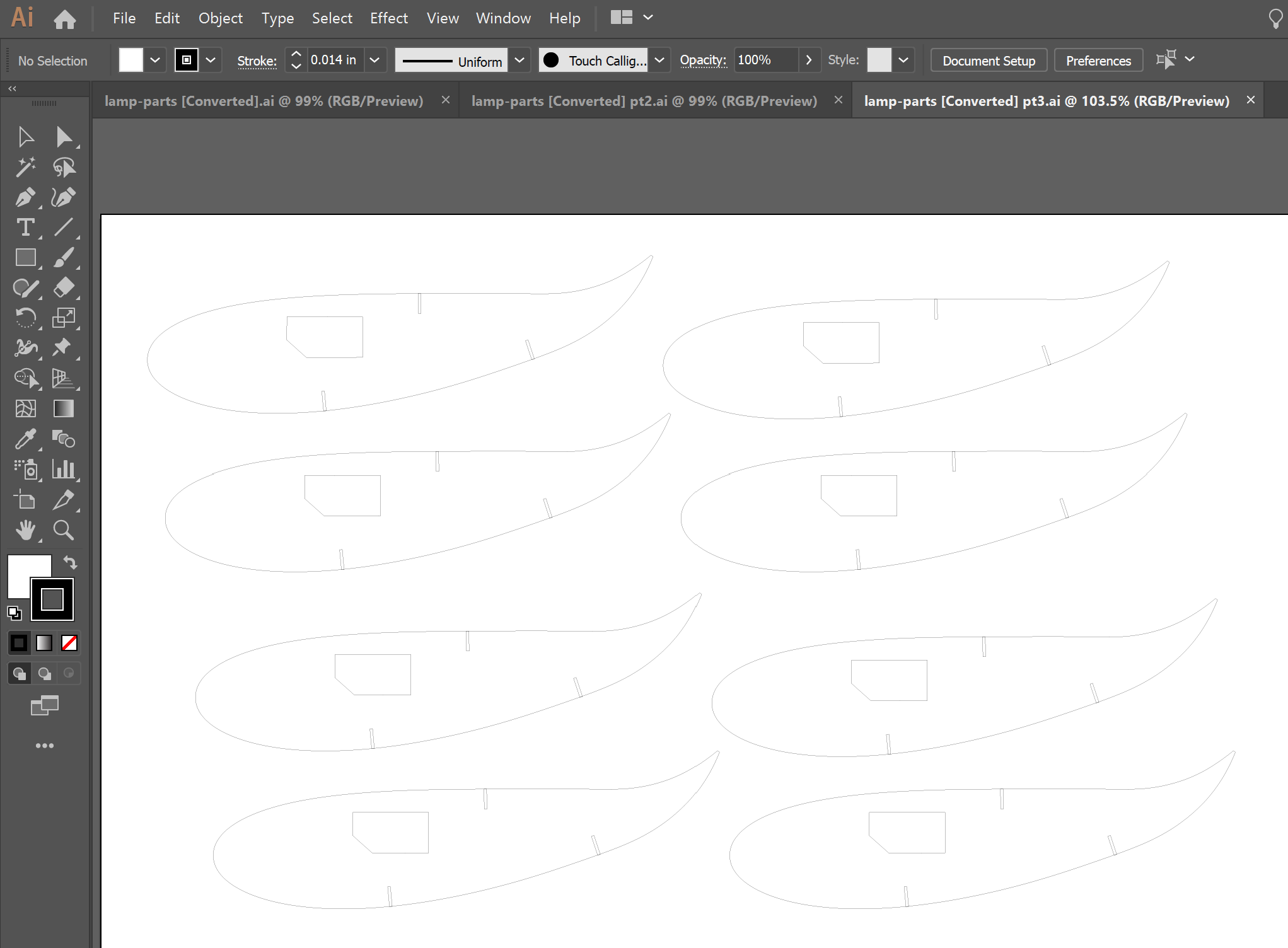
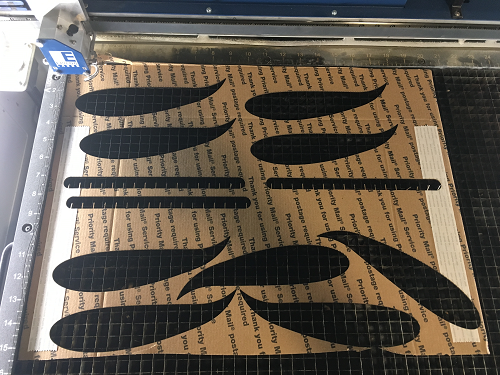
Earlier builds taught me to line up carefully and be patient with the spars. First, get all the airfoils lined up with one spar on top.

Now carefully slide the slots into each other.
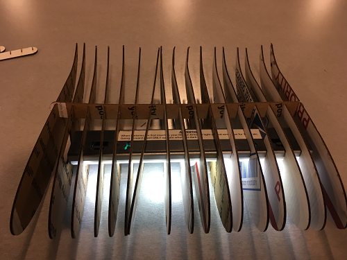
So far so good. Flip it over, put it on the edge of the table so you don't crush the trailing edges, and line up the second spar.
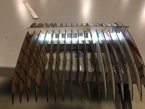
One more spar and ......
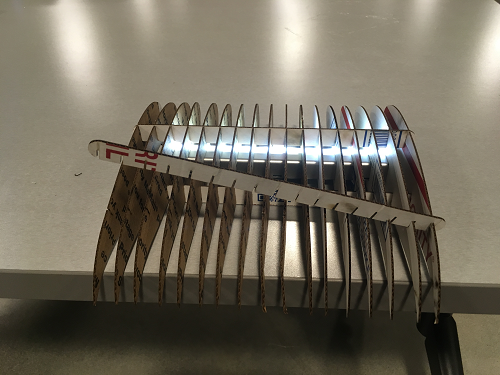
Done!
