Leo's Assignment 1: Laser-Cut Construction Kit!
Here is all the documentation for assignment 1!

Here is all the documentation for assignment 1!
Started by building a test gauge line-by-line. That was painful.
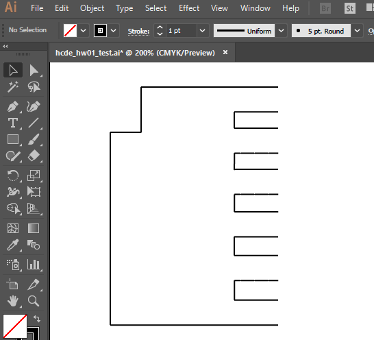
Figured out I could overlap separate shapes for cutouts. That was easier.
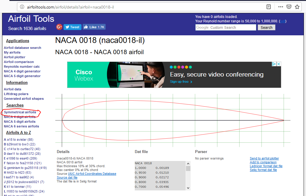
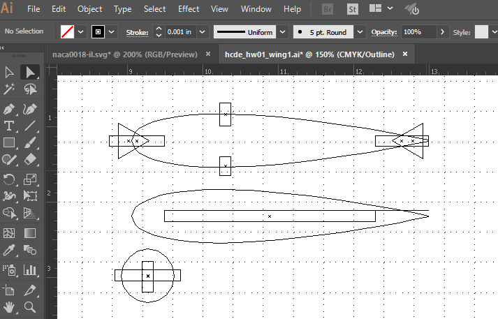
Figured out how to export actual NACA Airfoils as SVG from arfoiltools.com, then import into Adobe Illustrator.
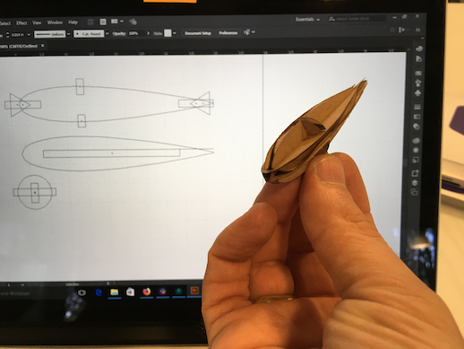
Also learned the importance of using layers cut the small inner parts before the large outer ones.
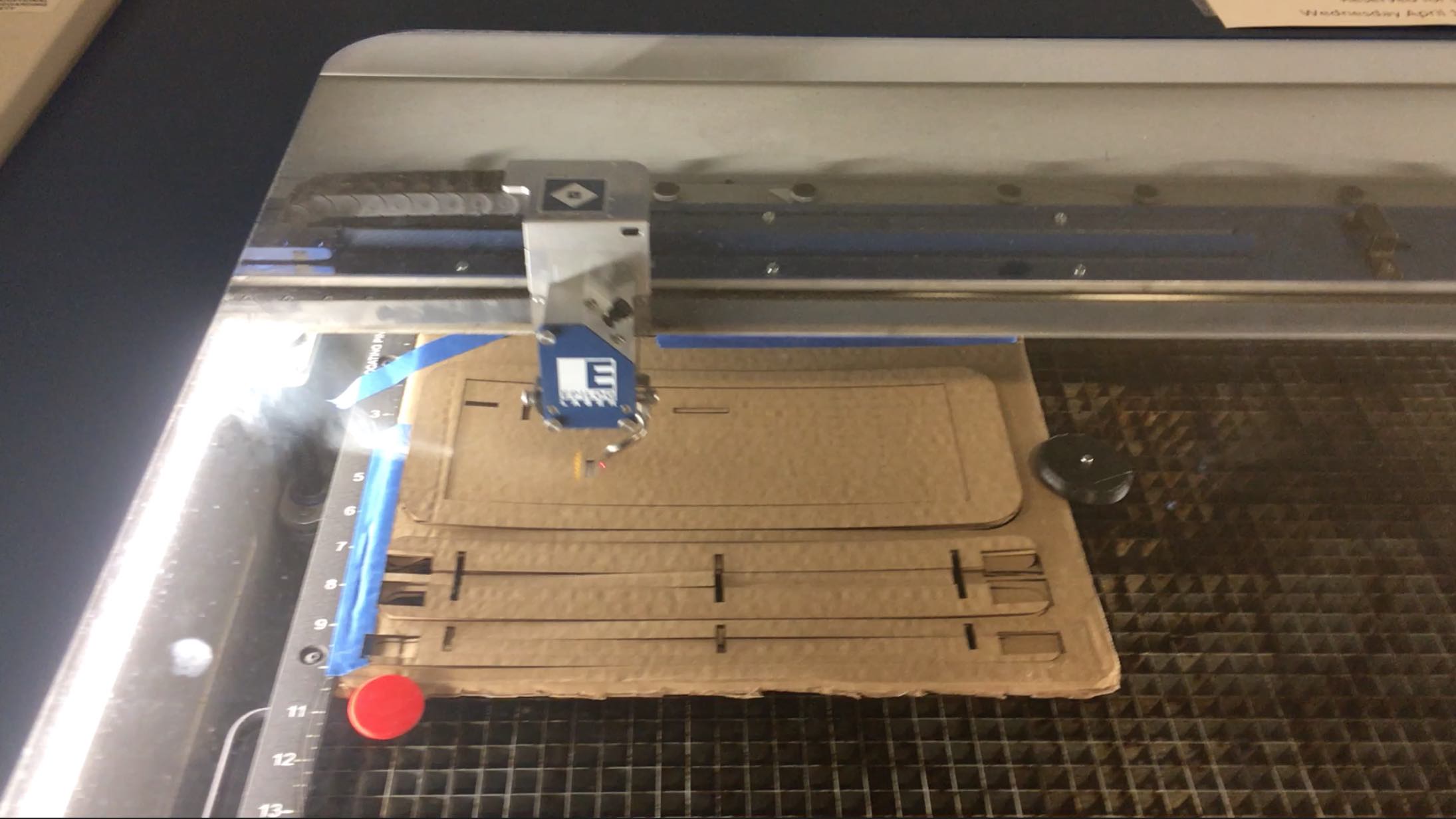
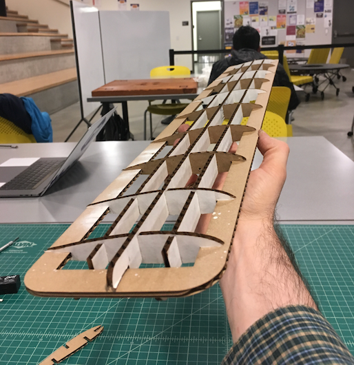
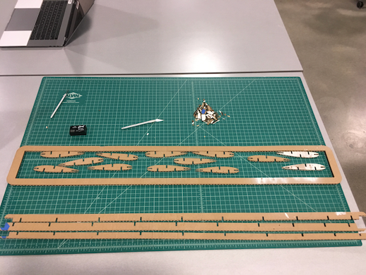
Having figured all that out, I could make a three-foot wing with nine ribs, three spars, and a "hoop frame" holding them all together.


Super Mega Epiphanies
Available on github.com at https://github.com/LeoSalemann/LeoSalemann.github.io/tree/master/hcde598/hw01
First thing I gotta do is make a "gauge" with different slot thicknesses. My calipers give me a thickness of 0.1580 in. Adobe Illustrator seems to stop at 0.01 inch increments. Okay, we'll make slots at 0.16, 0.17, 0.18 0.2.
I was hoping I could draw a rectangle, add some points, and cut things out. Adobe Illustrator doesn't seem to let me do that (not without a fight, anyway), so I'll go line by line instead. Not has hard as I thought, once you start copy/pasting the repetitive lines.
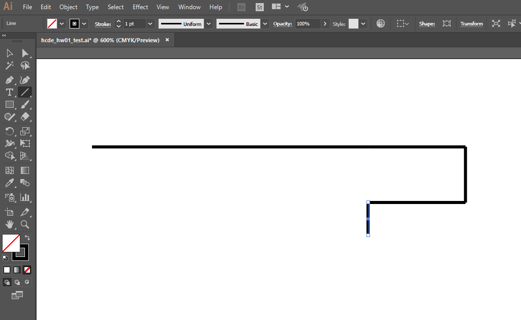
Heh. Here's an idea. Imma put a notch at the top of my gauge, so I know which end is which -- 0.016 will start at the notch.
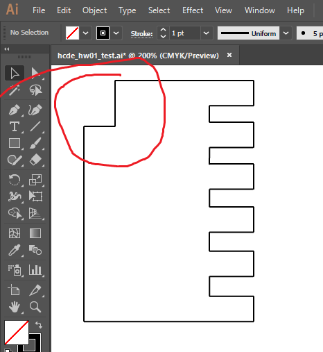
Now I gotta figure out how to make the chamfers. Gonna need to chop off my "end lines" ....

Add some angled chamfers (thank you copy/paste/flip-vertical)...
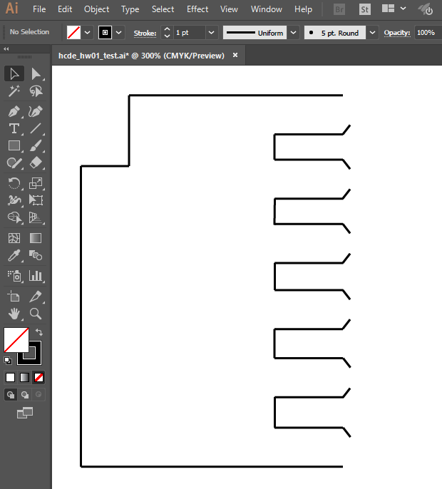
And reconnect the ends!
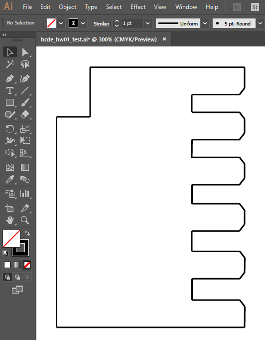
Okay, one more copy/paste so I have a pair, and it's off to the lasercutter!
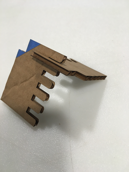
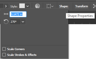
Well, crap. Even my tightest slot is too loose. Need to figure out how to see sub-tenth line lengths. Aha! clicking Shape gets you a form that lets you set exact length and angle. Going to change up my slots to be 0.146 0.148 0.150 0.152 0.154.
Aha! Adobe Illustrator provides a Shape toolbar item that gives you full control over line length!
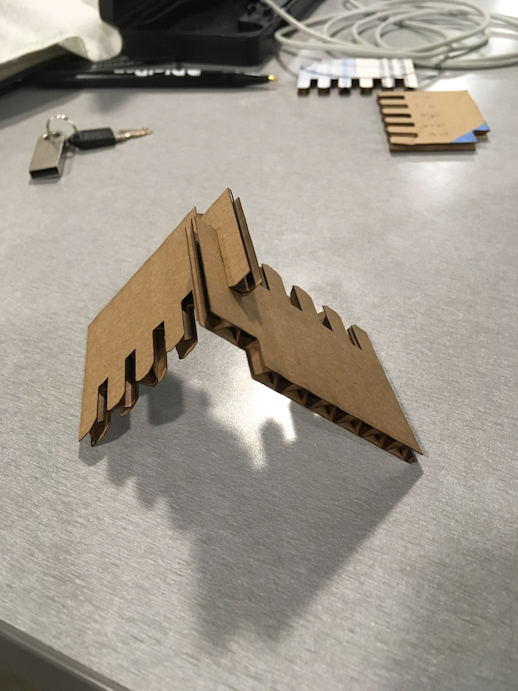
Success! ...just barely. The tighest slots (0.146 in) fit great. Tempted to make that my new midpoint and try for even tighter, but it's getting late and I need my beauty sleep.
Okay, it's been a couple days since the gauge build. Imma build a frame for a wing. Grab a legit NACA Airfoil, cut some notches in it, replicate, and include some more parts for the wing outline and a spar or two. I need 12 parts, so ... a wing outline, a spar, ten airfoils. Maybe a few more spars and less foils.
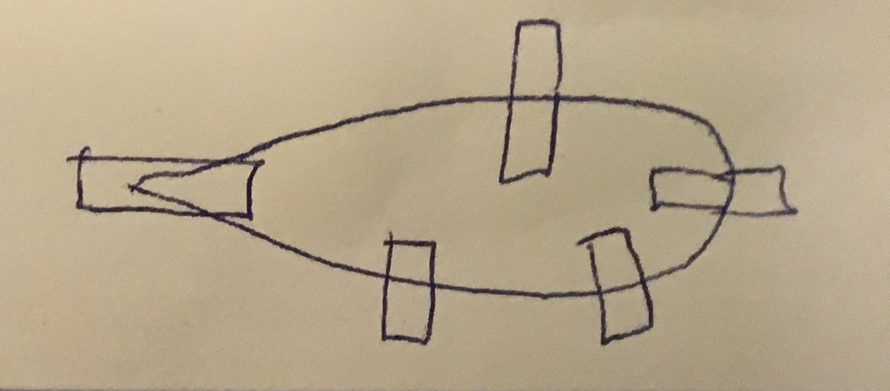
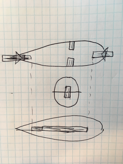
I've had another epiphany! I shouldn't need to do a bunch of line-by-line tedium like I did for the gauge. A simple overlapping rectangle should do just fine! Add a triangle, and I can get a chamfer! Don't know what I'm talking about? Here's a sketch:

Okay so let's try this. I'm gonna find a symmetrical airfoil, and make a little "3D teardrop" like this:
First-off, let's find an arfoil on arfoiltools.com, download as SVG, then import into Adobe Illutrator. This one looks promising.

The SVG loaded into Adobe Illustrator okay, but it inlcuded all the gridlines and titles and junk with it. After learning a bit more mouseology, I could isolate the airfoil. Add some rectangles for slots, triangles for chamfers, and we're ready to print.

Not bad. Used a lower power setting so some of the cuts didn't go all the way through. Had to do a bit of touch-up with an x-acto, but they came out.
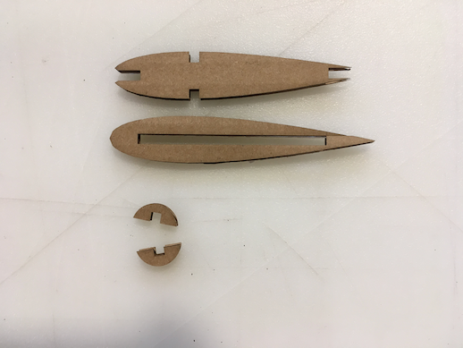
Pretty happy with how things assembled. Nice flush fit between the circle and the two airfoils. Need to make the parts larger next time, and avoid ong thin tapers. Also keep up with those triangle chamfers.

Right, then. Our little "drop tank" test proves this will work; let's make a wing! Back to the sketch book. We'll want a "rectangular hoop" for the basic wing frame. Then a bunch of airfoil ribs, and three spars. So to meet requirements, we need at least eight ribs for a total of 12 parts.
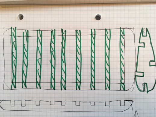
Well, that was a headache. LOTS of little elements to line up. Had to draw a bunch of guidelines. Which I ALMOST FORGOT to delete before printing.
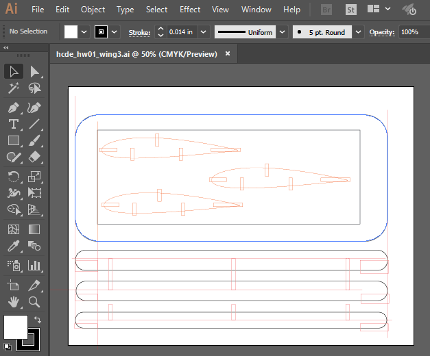
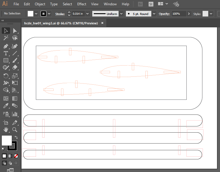
Headache #2. I had my airfoil set up as a library element, so I lost it when I copied my ai doc over to thumb drive to print from one of the UW MILL machines. Now let's try printing ....
I've learned a valuable lesson about print order. Pretty terrifying to watch some parts "scallop up" before the print's done. Everything came out okay, though.

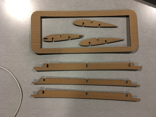
Headache #3. I discovered I forgot some of the rectangular cutouts. Had to improvise with a utility knife, but built myself a mini wing.
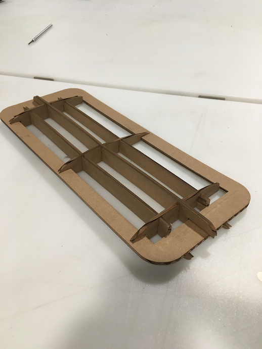
Last night, I drew out my big giant wing, but didn't have time to print it. This morning, I added chamfers. Before I print anything, I need to find a way to control which parts get printed in what order.
Need a layering system like this:
Looks like I can separate by art boards. Try that.
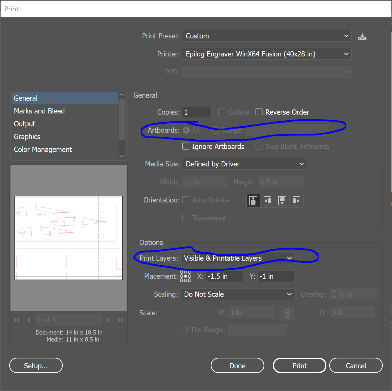
I don't think artboards are going to work, they just make separate pages next to each other. I'll try layers instead
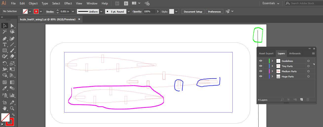
Printing by layers was highly successful for the second "mini wing." Confident and ready to move on to main wing. Also, two mini wings are 14 parts total, so I kinda met the requirements already.
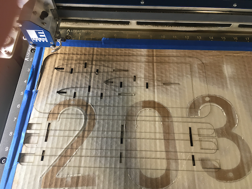
Okay, time to set up the layers for the main Big Wing.


Putting all the layers together, you can see how the guidelines help to keep all recuagular cutouts lined up. You can also see how it would utterly destroy the ouptut if we actually printed them.

Printing by layers was pretty easy. Just selectively turn one layer on and all the others off, and make sure print mode is set to "Visible and Printable Layers" not "All Layers."
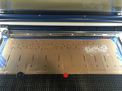
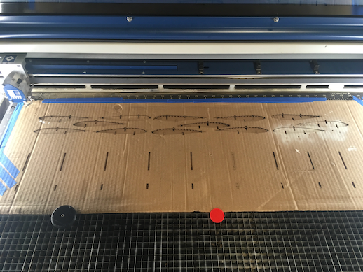
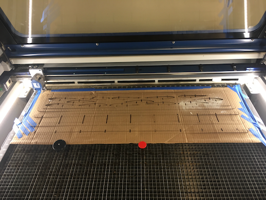
Crap. A lot of the small parts didn't cut all the way through. Forgot to set my power at 100. Time for the x-acto knife again.

On the plus side, the build went pretty easy.
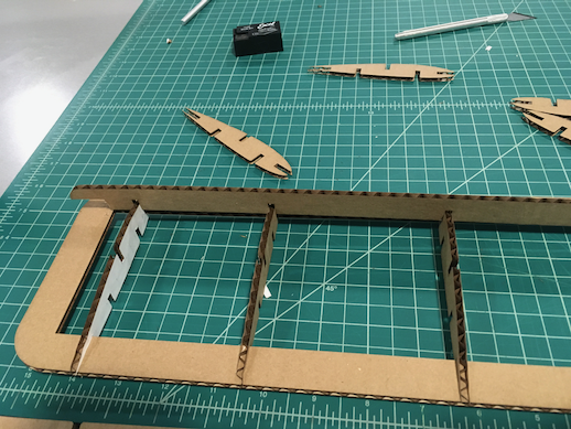
Not bad. Pretty happy with the way the wing spars meshed into the airfoils; too bad the front edge of the frame juts beyond them. Looks like I didn't have the airfoil & cutouts properly aligned. Good enough, though for a proof of concept.
